Tuesday, 28 June 2011

Trust thy Model (and don't be an idiot).

The 3d model of my setup has been a great help in many ways, one of which is that it is easy to see if parts collide with each other. Great care was taken that there is enough space for all individual parts, with one exception: the projector. The projector has to be mounted from the ceiling as it would induce too much vibration into the setup if we mount it on the frame. Because I have raytracing diagrams I know exactly where the projector has to go and that's where it was placed in the model. It also showed me how it wouldn't fit in where I need the projector. In the picture below you can see the model and how it predicted impending doom. Somehow I was convinced if I just ignore the problem for long enough it will go away. After trying to hold the projector in the right location it became clear that it didn't.

The model showed how the parts would collide in the real world setup. Ignoring the problem didn't make it go away. The collision looks smaller than it really is because the projector holder requires more space than in the model.

To fix this, the origin of the picture and thus the location of the projector had to be moved. Now there is a spectrum of solutions for this, ranging from clever to... the other extreme. My first attempt was clearly located somewhere close to the opposite end of clever. To re-locate the projector I introduced a second mirror that would deflect the beam away from the black frame, here is the re-calculated diagram:

You can see the mirror + mirror holder at the top.
This new mirror would do two things: lower the point of origin and change the projector angle, both together mean the projector will not collide with the frame anymore.So I happily modelled the mirror holder, ordered it from a 3D printing company, got the new mirror and put it all together. The new mirror overlapepd the convex mirror at the back, but this wasn't going to be a problem since there is no screen behind the animal.
The new construction with the new mirror overlapping the convex mirror. This however is irrelevant because that section of the convex mirror is unused.
In theory this would work, in practice however this new change meant that the projector wouldn't focus on the screen anymore. I haven't investigated exactly why but my suspicion is, because I'm using normal household mirrors which essentially consist of a glass plate and a reflective coating at the back, the light was refracted in a way that made it impossible to focus.

Only then it occured to me that if I just change the angle of the flat mirror underneath the convex mirror by a few degrees I get a much simpler (read: much better) solution that actually works. Arranging the flat mirror in a steeper angle lowers the point of origin and moves it further away from the mirror, if you look at the first figure you can see that this will clear the frame easily. With the palm of my hand across my face I (virtually) tilted the mirror by only 5 degrees and started recalculating the path of light. The result of which you can see here:

The flat mirror was angled by 5 degrees (from 23 to 28 degrees) and lowered by 1.3cm, which moves the point of origin significantly. Right is before, left is after.
The only downside of this is that the experimenter might need to duck under the projector now while placing animals and exchanging electrodes, but otherwise there are no changes to the setup.

There was one benefit of the mistake I made however, the mirror holder for the second mirror was made on a 3d-printer by an external company. The cost was low (£30) and the quality ok. I wouldn't use it for anything that needs to be precise or clean, but it's ideal if you need something with an odd custom shape. Should I ever have similar requirements I know now where to go.

The next step is to set all of this up in the real world. The difficulty here is arranging all the parts correctly and at the right distances/angles from each other. With all the odd shapes it is difficult to use rulers, tape measures and spirit levels (I've actually got a digital one that gives me a angle readout). Further, getting the projector mount into the right location won't be easy either (how do you mark a point mid-air?). Once all that is done however I'll finally be able to test my virtual reality which I'm programming on the side right now.


Construction Notes

Calculating the requirements for the second mirror wasn't a great effort since the law of reflection is very simple. The centre line (red in the above pictures) was my starting point. I cut it at an arbitrary point somewhere in the top third and dragged the point of origin to a more suitable location. Based on the new angle I calculated the angle of the new mirror and did the raytracing for the entire cone (yellow lines).

The dimensions of the new mirror were calculated by constructing the light cone (see article Aperture Science) and intersecting it at the level of the mirror. This gave me the ellipse that needs to be deflected onto the round mirror underneath the convex mirror. Below you can see that process. What I didn't take into consideration at this point is that the reflective coating of the mirror is at the back, which A) alters the distance from the point of origin and B) refraction of the light changes the angle of the incident ray and therefore also the ray of the reflected ray. All this however was inconsqeuential due to the fact that the projector wouldn't focus on the screen anymore, which I think is too due to effects refraction. I haven't tested that suspicion though as my subsequent solution of changing the angle of the round mirror made the newly introduced mirror redundant.

Calculating the mirror dimensions. The pink triangel is the light cone, and the green lines represent the ellipse and the mirror dimensions respectively. The ellipse is very long and narrow due to the extrem angle at which the mirror is intersecting the cone.

Modelling the mirror holder was straightforward and it was very easy to order the part from the 3d printing company (3D Creations Lab) since all I had to do was upload the 3D model of the part on their website. The key requirement of the holder is to hold the mirror at the correct angle. The holes at the front are there to reduce the amount of 3D printing material, which lowers the overall cost. I used simple double-sided tape to put the parts together.


Model and reality.

Below is another view, holding the camera to the new point of origin. The calculations seem to be correct, from that point of view I can cleary see all of the round mirror, the convex mirror and all of the screen. However, it was difficult to focus the camera.

Placing the camera at the point of origin showed that the calculations were right, but focussing was difficult.


After I decided to abandon the new mirror in favour of the simpler solution mentioned earlier, I removed the mirror holder and mirror and everything was back to normal.

Friday, 3 June 2011

Silence and Simplicity

what could pass as some sort of advert slogan is really just my attempt to improve the treadmill.

Prof. Hans-Jürgen Dahmen, one of the main people who designed the very first rodent virtual reality system (Hölscher et.al. 2005) has given me a lot of advice and information since I started the project and I'd like to thank him at this point for that. Part of his advice was that having 8 air inlets is unwise, which, after some thought, made perfect sense. Here is why: according to Bernoulli's Principle a larger tube diameter means slower fluid/gas speed. This in turn means less noise which is beneficial as it causes less stress in the animal.

So instead of 8 inlets with an outer diameter of 6mm I now have one single inlet at the southpole with 12mm outer diameter. The surface area of a 12mm crossection is still smaller than the surface area of eight 6mm tubes, however one has to consider that wall thickness on 6mm tubes is the same as on 12mm tubes, which makes a significant difference.

Single 12mm inlet at the southpole instead of 8 inlets.

Regardless of all that though, I found out that by far the biggest source of noise is the valve which regulates air-flow from the compressor. After disconnecting the treadmill and just opening the valve I realised that the noise produced is almost deafening and for a mouse that must be the equivalent of having a jet engine blowing right into it's ear - continuously.

The company that sells the connectors and tubing also sells noise silencers but after a brief test I can say that the efficiency of these units is questionable. However, another useful tip from an engineer worked a lot better: put a generous amount of tubing between the source of the noise and the output point. In my case that is between the valve and the treadmill:
A 20m coil of 8mm tubing between the valve and the treadmill reduces noise significantly. The valve with the red handle is the main source of noise.
The result is a much quieter treadmill, here are two videos to compare the amount of noise, first the loud one:

And here the dampened one:


It's still not exactly quiet, but it certainly has taken off a lot of noise. Should this amount still be a problem I can still think of other ways to reduce the noise.Using a 12mm or 16mm inlet tube and 20 metre 'buffer tubing' of the same diameter for example would probably take noise down another notch. The ball starts turning by itself in the videos but that is purely because I haven't inserted the tube into the cup straight, it just needs some clamping down of the tube to make and keep it straight.

The single inlet at the south pole works well. Because the surface of the cross section is if anything a bit smaller than that of eight 6mm tubes there isn't much difference in terms of performance as far as I can tell. Dr. Dahmen noted that 3-4cm would probably be ideal for me and I might do that at some point should there be a need to improve this treadmill design, but for now I like the simplicity and efficiency of a single inlet.

Single inlet treadmill. Works very well and is much more efficient than the complicated 8-inlet system. I like efficiency.


With this improvement of the treadmill I hope that a mouse will have the pleasent experience of a cool summer breeze stroking its fur rather than the feeling of sitting on a jet engine.


References:
 
Hölscher, C., Schnee, A., Dahmen, H., Setia, L., & Mallot, H. A. (2005). Rats are able to navigate in virtual environments. Journal of Experimental Biology, 208(Pt 3), 561-569. Co Biol. Retrieved from http://www.ncbi.nlm.nih.gov/pubmed/15671344

Wednesday, 18 May 2011

Aperture Science

Looking the the flat mirror you might realise that the rectangular output of the projector won't fit on it entirely, and that the light that misses the mirror will go straight on the screen, thus interfering with the actual virtual reality. One solution would be to but a plate behind the flat mirror which catches the excess output. However, due to space constraints an aperture is the better solution. There is a lot to say about apertures and you can use it for many purposes/effects in optics, but I'm using the term aperture in its most general meaning, here is the first line of its Wikipedia article: "In optics, an aperture is a hole or an opening through which light travels." Yeah, great word for such a simple thing. In microscopy you use an aperture to catch scatter light and thus improve sharpness and contrast of the picture. Here we use it to block unwanted background light. The best  location to mount the aperture in our case are the two black construction cubes you can see in the picture below.

The Aperture will be mounted to the two black cubes which also hold the poles for the flat mirror.

Here is a side view of the entire model. You can see here to location of the projector and at which angle the rays will fall onto the screen. The convex mirror profile was chosen to maximise coverage.


Because we are cutting a plane through a cone at an angle we will need an eliptical opening. Now, if you are a straight A student you'll know how to calculate the dimensions of the eliptical cross section at the level of the intersecting plane. But if you are, like me, a lazy git, you'll just punch it into the modelling software and make the computer do the work.

First of all, we take the projector output and revolve it around the centre axis to get a solid body which we can use for modelling. With that you can create a plane in the desired orientation and level as I've done in the picture below. For clarity I made the raytracing lines invisible. You can probably guess where I'm going with this now.

By taking the raytracing lines and revolving them around the centre we can make a 3-dimensional representation of the projector output.

Next step is to slice the model at the level of the plane. Sounds like a lot of work but really all you need to do is hit F7.

The cone sliced by the plane.

Now all you have to do is project the cut edges of the cone onto your plane, create a sketch and extrude it.

Sketching a simple rectangle with the ellipse projected at its centre.
The extruded aperture with the requried opening.
Cutting the ellipse straight is suboptimal because the rays are passing through at an angle, but given how thin the aperture is (here it is 5mm, but it can be much thinner, depending on which material you use), it is negligible in my view. Here is the final picture:

Aperture mounted to construction cubes with bolts.

To turn the computer model into reality we can easily create a technical drawing which can be handed to the workshop. With sufficient annotation they should be able to create the desired part.

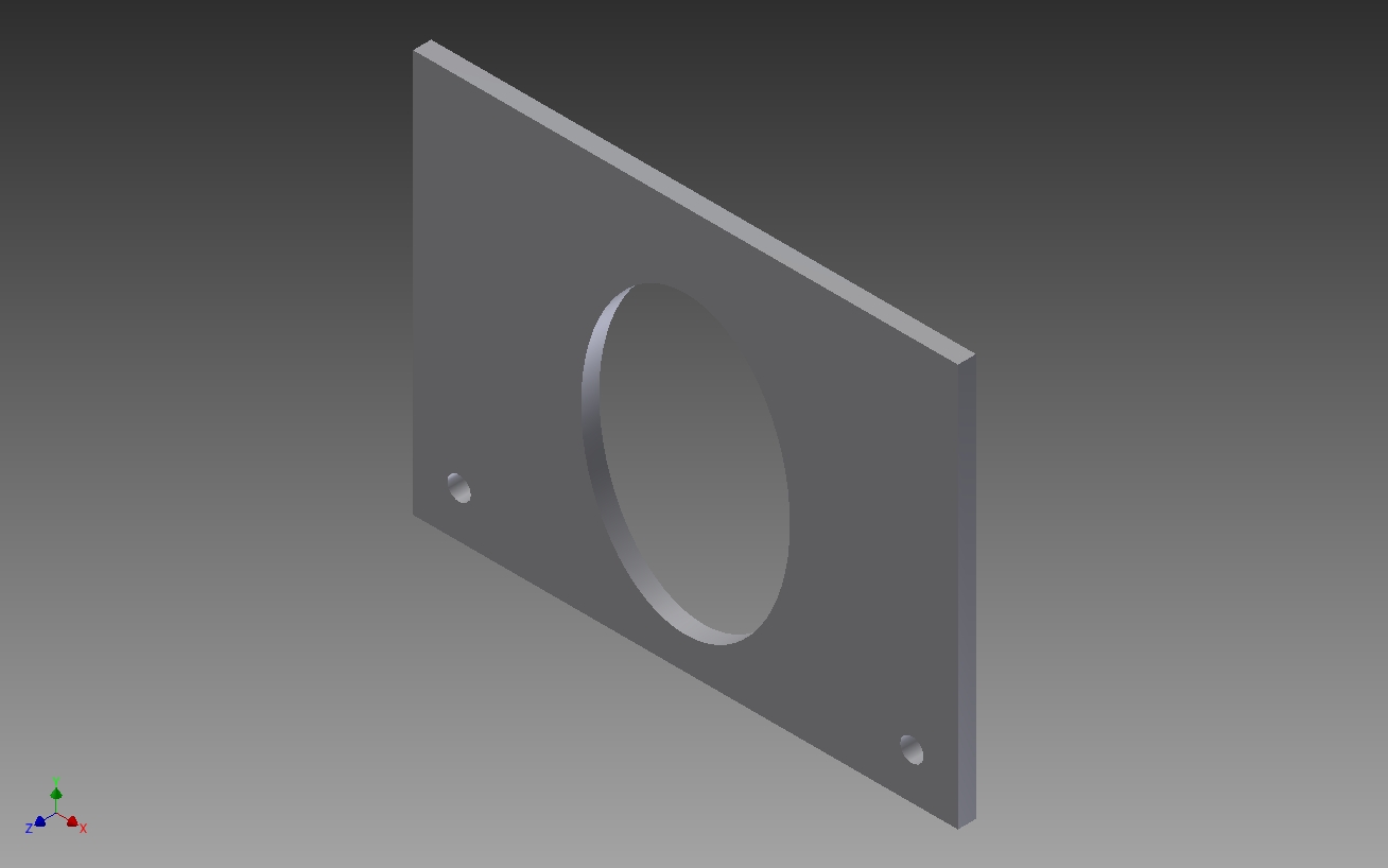
Technical drawing of the Aperture.
From here it is easy to order a plate with the required dimensions, drill holes at the right places and cut the ellipse out. Then two M6 screws will keep it in place. I hope I made my case for 3d modelling once again, it's hard to overstate my satisfaction.

EDIT:
Just a few words of clarification:
- the light cone cuts through the flat mirror, that is just me being too lazy to correct the model. I simply revolve the top half of the lightpath around the central axis, but because the cone is at an angle to the mirror it will cut through it.

- the initial technical drawing missed a few annotations, that is now corrected.

Wednesday, 11 May 2011

2 for 1 - Screen and Mirror

Mirror

It so happened that parts for both, the mirror and the screen were finished/arrived, which is why you get two updates in one post. Both parts of the setup are crucial and depend on each other. Here is why: The specifications of the angular amplification mirror (the convex mirror which deflects the projector picture onto the screen) depend on the specifications of the projector (closest focus distance, picture size at given distance) as well as the dimensions of the toroidal screen. So given how far away the projector has to be to focus, and what size the picture is at that point I need a convex mirror which deflects that picture across the entire screen. Here is a picture of my raytracing model to illustrate what I mean:

Raytracing: the top left is the origin of the picture. The extreme angles (aka throw ratio) and closest focusing distance were measured rather than taken from the projector specifications sheet. The mirror profile was calculated as described in Chahl and Srinivasan (1997) and the deflection angle was calculated using the law of reflection.


As already mentioned in my previous post, I conveniently modelled the construction that will hold the flat and the angular amplification mirror in Autodesk(r) Inventor(r) 2011. One thing to keep in mind is to keep the light path as unobstructed as possible to avoid shadows. Here it is again:
Model of mirror construction. An important design consideration is that the poles holding the flat mirror don't obstruct the light path significantly

And here is the actual construction:

To avoid scattered light to be reflected onto the screen the background of the angular amplification mirror has been coated with "blackout" material.
The base plate which holds the construction is mounted to the ceiling plate with simple M6 rods. The disadvantage of this is that I'm bound to the holes in the ceiling plate and I need to centre everything around the mirror.

Screen
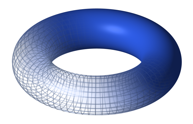
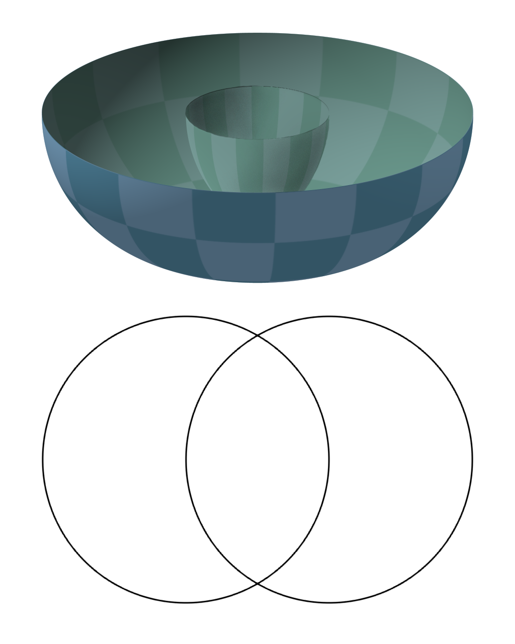
The screen has the shape of a torus, more specifically, a horned torus. However, we don't use an entire torus but rather the outer mantle only. A torus is an interesting geometrical structure, for example you can divide it into 7 regions that cover the entire torus, each region neighbouring every other. But that's completely irrelevant here. However, here is to illustrate the shape:
Top: normal torus. bottom: Cross section of the torus we are using.

The obvious question was: how do I put this shape together. In previous posts I mentioned a skeleton of copper tubes which will be used as a framework, but just as difficult to work as the framework is the actual screen material. Pufferfish, an Edinburgh based company that does spherical screens, kindly provided me with some of their screen material. Initially my plan was to print a template of each section on paper, transfer it to the screen material and cut the section which are then mounted onto the copper tubes.

As it turns out, the screen material had too many folds (I got it second hand) and didn't allow me to spread it out flat and transfer the pattern. However, I printed the template on canvas paper which appeared to have just the right stiffness for my needs. So I tried.

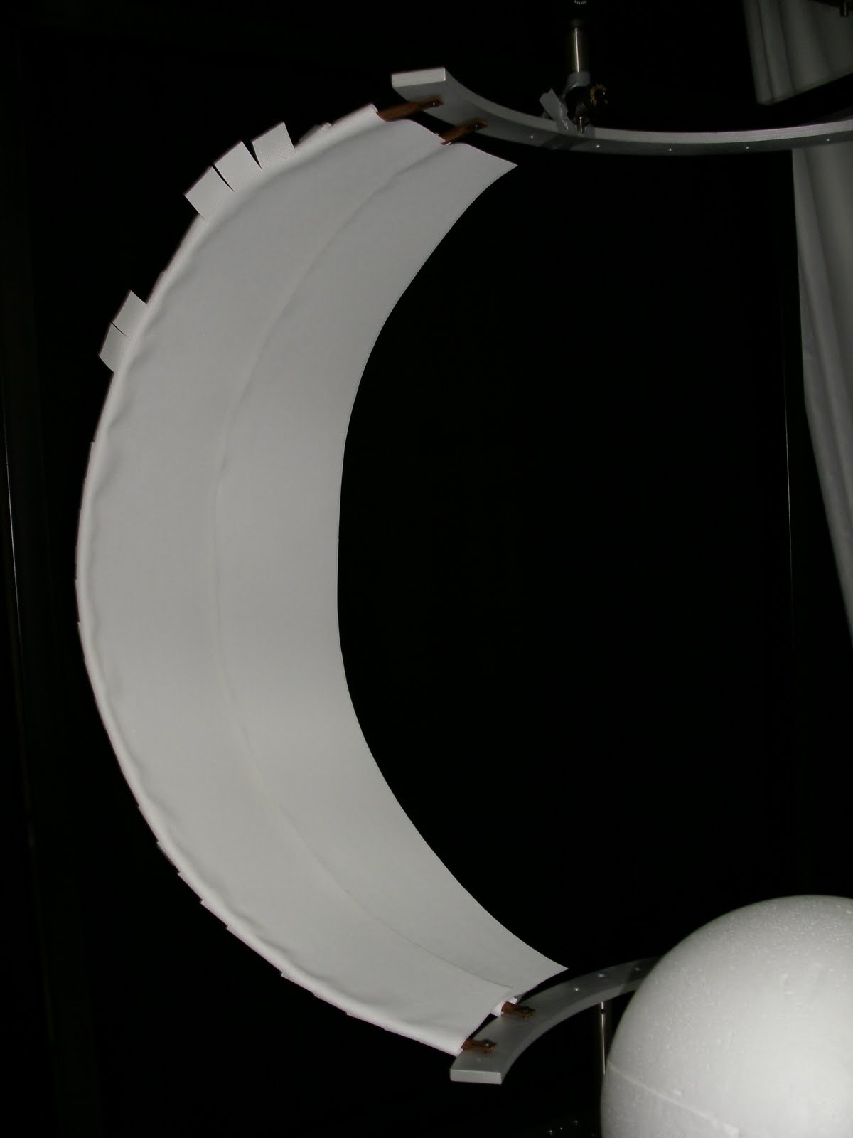
My first attempt of mounting the canvas onto the copper tubes failed as bending the paper around resulted in folds which of course would distort the picture. After trying a few different ways to mount the sections it became obvious that less is definitely more: Mounting the section on 2 points only, the top and the bottom, gives by far the best results. The material is stiff enough to stay in shape by itself when pushed against the copper tubes.

First failed attempt. Bending the canvas and mounting it all around the tube results in folds.
Less is more: mounting the canvas at the top and at the bottom and pushing it against the copper tubes works very well.
I've used an alternating technique: The first section was mounted to two tubes, one on each side. Then I left a gap and mounted another section. Finally, a slimmer section was mounted between those two, not on the copper tubes however, but on the sections themselves. You can see that in the above picture on the right.


Summary  
Screen and mirror put together looks pretty close to what the finaly construction will look like. Here are a few pictures:


Screen with mirror "hanging" from the ceiling. The mirror is a bit off centre but that will be fixed soon.

The back of the screen. It looks less even from the outside that it is from the inside. This is because some of the sections are overlapping.
Whether everything I've done here will actually work I will find out once the projector is up. Only then I'll know whether my raytracing was correct. Fingers crossed.

One thing you will have noticed in this latest blog entry is that I finally found the "add caption" button for pictures. Yes, that's how computer savvy I am. Now let me get on with programming the virtual reality.


Construction Notes


Mirror
The mirror construction is hanging from the ceiling plate. To achieve that I used a 10mm thick clear acrylic plate and drilled holes at the right places. The mirror is mounted with 4 M6 screws and the entire plate is mounted on 4 M6 threaded rods. I had to cut the rods into the right length, but once that was done it was very easy to mount it using nuts and washers. To attach the flat mirror, 1/2 inch diameter rods and right angle brackets (Thorlabs) where used as shown in the pictures above. The M6 construction cube at the base of the rods has M6 threads on each side which allowed me to mount it to the base plate with M6 screws and then just screw in the rods. The flat mirror itself is mounted on a L-shaped scrap piece of metal I got at the workshop. I drilled a 6.5mm hole into it and mounted it onto an 8-32 to M6 adapter thread with nuts and washers (the standard stud on the end of a 1/2 inch rod is 8-32 but I replaced it by the adapter).

The clear acrylic base plate. One thing to keep in mind when drilling holes into it: the material heats up quickly, so drill slowly and only drill 1-2 mm at a time then let it cool down briefly.

The blackout material. Small holes cut with a knife where the screws will go through.

Mirror mounted

Mirror and blackout material on the base plate.


The contruction as it is mounted to the ceiling plate. It's very easy to adjust the height like this, just turning the nuts a few times to bring it up or down.

The ceiling plate with everything mounted.
As posted earlier: the final construction. I've got a digital level to bring everyting into the right angle.

Screen
The screen is a rather tricky construction due to it's uncommon shape. The canvas paper has just enough stiffness to stay in shape without extra support, but any bigger a screen and one probably needs a different approach.

The sections were calculated in Octave (open source equivalent of Mathworks(r) Matlab(r)) and printed on canvas paper. My first Idea was to mount each section to one copper tube and connect it to the next sections with glue or tape. This approach however resulted in ugly folds as described earlier. What worked best for me was mounting one section on two tubes and then connecting those section with slimmer strips. Hope my description isn't too confusing, but if it is feel free to drop me an email. I've mounted the sections to the tubes and to each other using ordinary super glue.

The leftmost section is mounted on a copper tube on each side. The gap you see in between was covered by a thinner section that was glued to the flaps you see at the top and at the bottom.


The section as it was printed on the template. Unless you really like blisters on your hand you should invest in a good pair of scissors.

Getting there.

Entire screen without the mirror construction. You can see the copper tubes shining through the material, but with any luck that won't be visible once the room is dark and only the projector is shining on it from the inside.


References:
Chahl, J. S., & Srinivasan, M. V. (1997). Reflective surfaces for panoramic imaging. Applied Optics, 36(31), 8275-8285. OSA. Retrieved from http://www.ncbi.nlm.nih.gov/pubmed/18264368

Saturday, 23 April 2011

In the Land of the Machines

So it was time to do the first stage of the screen: the copper tubes that will hold the sections of the screen. Copper has a very handy property: It's soft initially, but the more you bend it the more rigid it gets, making it ideal for my application. Since it is next to impossible to get a screen of toroidal shape it will be put together by individual sections, each of which will be attached to the skeleton. This picture shows the screen skeleton made out of copper tubes in the 3d model:


Once again I had a field (half) day at a workshop, this time however it was the physics workshop as opposed to the (very small) neuroscience workshop where I did the black frame. The machinery there instills fear and awe. You wonder what kind of people can tame those machines that appear to be only a step away from growing arms and legs and start crushing everything in their way. There are rumors that on every full moon the technicians sacrifice a virgin's eldest child to appease the machines.

Anyway, after a short chat with the lead engineer we've decided to bend the copper tubes around an appropriate shape. To get that shape we drew a 23cm radius circle on a board and drilled screws halfway in around the perimeter (if you don't know what I mean, look at the pictures below). This allowed me to bend the copper tube around the circle and end up with semi circles of the right size. We placed the screws slightly inside the the 23cm circle because the copper wouldn't stay exactly in the shape I bent it but rather spring back a little bit, so if the circle was exactly 23cm we had ended up with a larger radius.

Above you see the method to bend the tubes around the ring of the screws. Bending full circles allows me to get 2 at a time. My fingertips were hurting after 4 out of 20 semi-circles. The bottom picture shows how I fixed the start of the tube so I don't have to hold it permanently.

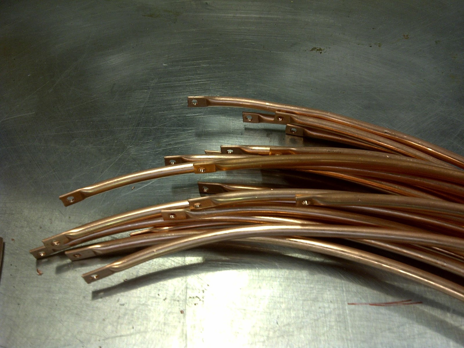
21 semi circles. Why 21 when you only need 18? So I have 3 for testing purposes. Why an odd number when you always get 2 at a time? Because I'm a retard and cut one too short.

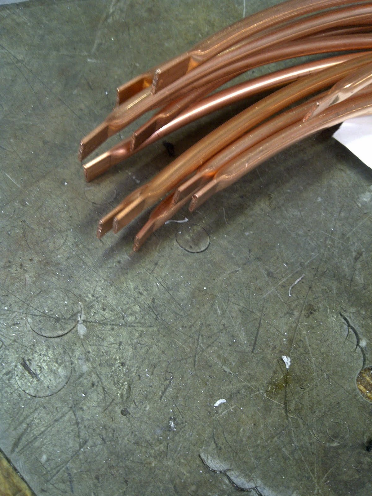
 In order to mount the tubes to the rings (see previous post here) I had to flatten the ends and drill a 3.5mm hole into them. This would allow me to fix the tubes to the ring with M3 screws. Because copper is quite a soft material the holes had to be cleaned up a bit. This was done with a drillbit of bigger size which was turned manually to take of the excess copper left by the drill:


Bottom picture: the result of 5 hours work

Back in the lab I've mounted to top and bottom ring and mounted three tubes to see whether they fit. And they did. Below are a few pictures of the tubes on the rig, for a short while I was tempted to mount all 18 to make it look really nice for the pictures, but putting then first 3 on made me realise that putting all of them on and taking them off again will give me carpal tunnel syndrom.

The tubes fit well and look as I imagined (read: modelled) it.

The next step is to cut the screen sections into shape and mount them on the tubes. In the first instance I will use tape to connect the sections, depending on how visible they are if the projector is on I might have to find a less visible solution. And for those who made it to the very bottom of this post, here is a detailed model of how the mirror will be mounted from the ceiling. It will be hard to oversee the similarity to the Harvey et. al. (2009) setup and I want to give it the according credit at this point. A happy easter everyone!


References:

Harvey, C. D., Collman, F., Dombeck, D. A., & Tank, D. W. (2009). Intracellular dynamics of hippocampal place cells during virtual navigation. Nature, 461(7266), 941-946. Nature Publishing Group. Retrieved from http://www.ncbi.nlm.nih.gov/pubmed/19829374