Here is the long promised follow up to
this post.
In brief: I want to build a heating mat that keeps animals warm while under anesthesia. Three components are required for that: a heating blanket, a thermometer (thermocouple to be correct) and a
PID controller that regulates the heat output to keep it at a set point. In other words: if the mouse body temperature drops, the heating mat gets warmer to compensate. In the previous post I put together such a system on a prototyping board and here I document how I put this system into an instrument case for use on a bench.
The reason why I made an effort to put everything inside a well organised case and not just throw the prototype onto the bench is threefold:
- We will use this during surgery in a sterile environment, therefore having something that can be cleaned easily is imperative.
- Everyone should be able to use it, not just myself. For that reason it is important to keep it simple and intuitive.
- Any instrument used in the office or lab needs to pass electrical safety testing and I have serious doubts my protoype with exposed mains contacts would have fared well in the test.
The Box
While there are loads of generic instrument casings out
there I decided to take a nice one to make the instrument look as professional
as possible from the outside. After all, it has to blend in with other
top notch scientific equipment. More importantly though, I don't want to
give our beloved and omnipresent health and safety inspector any reason
for concern. She really has enough on her plate with untidy cables,
sharp screwdrivers murder weapons lying around and
expired electrical safety stickers. Truly, we are blessed with a
guardian angel who spots danger where lesser people (such as myself) stare certain death
in the eye without even noticing.
To keep things
simple, there is one mains connector and power-switch at the back. At
the front we have the connector for the thermocouple and the heating mat
along with the PID controller display and the buttons to program it.
The heat-sink is screwed straight onto the back panel with the op-amp
mounted onto a thermal transfer pad on the other side of the panel.
Since heat-sink as well as panel are made of aluminium there won't be any
trouble with heat-transfer.
 |
| The layout idea. |
 |
| The mains
inlet contains a 1A fuse. It wasn't that easy to wire up mains connector
and power switch. It's one of those things where every seller assumes
that you know what to do and therefore don't provide wiring diagrams. |
The
most time-consuming work after soldering was to cut the front and rear
panel. For that I used a mill to cut around the edges. This was followed
by filing the corners until the part fitted in. It doesn't have to be
the cleanest job in the world as all panel-mounted parts have some extra
cover material around the edges to hide the ugly.
 |
| Milling |
 |
| Filing |
 |
| Placing the part. They either clip in directly or have a retention clip. |
 |
| Rear panel done. |
 |
Repeat for front panel.
|
After clipping in mains inlet and power switch as well as heatsink I placed the amplifier in the case. After that I grounded the front, rear and side-panels for safety reasons. Top and bottom panels as well as corners of the case are not conductive and therefore don't need to be grounded. Finally, the rest of the components just about fitted in and I was able to put the lid on the case.
 |
| One policy regarding instrument safety around here is that if there is a
mains-cable running into a device the housing needs to be
safety-grounded. Therefore all conductive panels are connected to the earth of
the mains inlet at the back. |
 |
| Add the 12V DC
power supply for the heating mat, put in the PID controller as well as
the connectors and this is good to go. In the top right hand corner you
can see the op-amp and the heat transfer pad. |
 |
| Once the lid is on, the chaos is gone. |
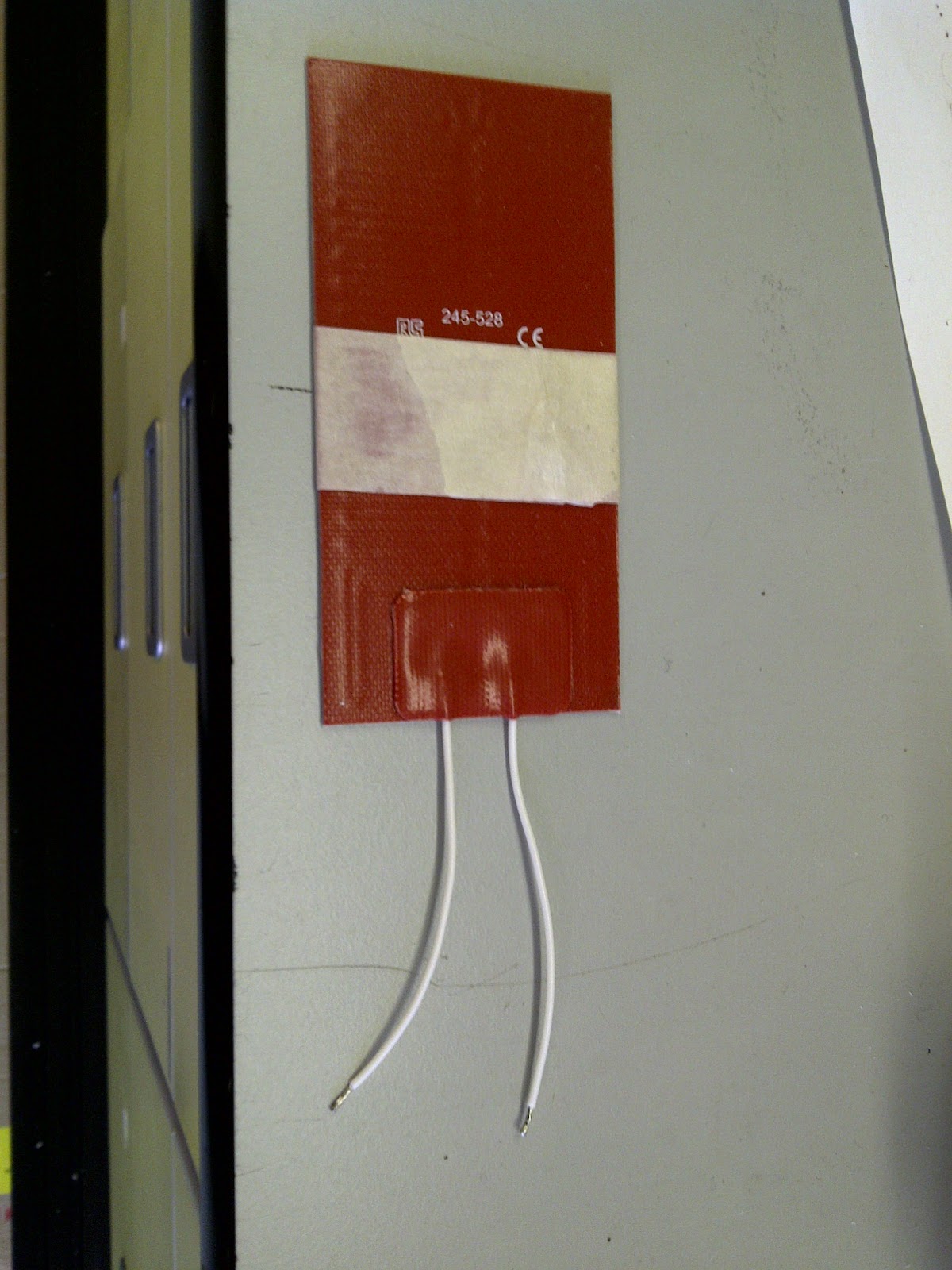
Blanket
Instead of soldering the heating blanket directly to the output I wanted it to connect to the outside of the box. That way it was interchangeable so if it breaks or has to be exchanged for some other reason there is no need to open up the box. We chose a simple 3-pole connector that is usually used for microphones but has also found its place in various scientific instruments. Here are a few pictures of the construction process:
 |
| Only keep a stub of the original cables. |
 |
| Any cable with 2 strands will do. I recommend something fairly flexible so you can position the blanket easily during surgery. The peeled back portion it the shield which will be grounded. |
 |
| Do a better soldering job than I did. On the left you see the shield being soldered to the 3rd pole. |
 |
| Put the connector together. |
 |
| The finished mat. Heat-shrink is used to protect the soldering joints. |
Thermocouple
The only component I had to buy from a scientifc equipment supplier and the price made me cringe. Industrial thermocouples cost a fraction of this but I'm not confident using them with animals. Otherwise its a standard t-type thermocouple so I could just plug it into the PID controller.
 |
| Its blue. |
Amplifier
The non-inverting amplifier used to drive the the mat including an RC filter for the PID output (see previous post for more information) has been soldered onto a strip board. The heat-sink has been up-sized as well as the previous, smaller one got hot to the touch.
 |
| This could have been a lot smaller had I used a matrix board instead of a stripboard. The blue feet allow me to simply stick the board to the base plate of the box. |
|
|
Finally
 |
| ID tag and electrical safety sticker. A proud moment. If you are in dire straits and you find yourself buying lab equipment from a shady person in a dark alley (who hasn't been there?) please check the appliance ID. If it is CCNS00206, be so kind and return it to me. |
 |
| Testing with direct feedback. |
To my surprise everything worked the first time around. No mixed up
poles, no loose connectors, I switched it on and it worked. I guess you
automatically put in that extra bit of caution when playing with mains
power. What is left at this stage is to tune the PID controller. It is
important to start with careful values as there is a significant lag
between increase in heating mat and rise of mouse body temperature. More
information on that on
Wikipedia.