Mirror
It so happened that parts for both, the mirror and the screen were finished/arrived, which is why you get two updates in one post. Both parts of the setup are crucial and depend on each other. Here is why: The specifications of the angular amplification mirror (the convex mirror which deflects the projector picture onto the screen) depend on the specifications of the projector (closest focus distance, picture size at given distance) as well as the dimensions of the toroidal screen. So given how far away the projector has to be to focus, and what size the picture is at that point I need a convex mirror which deflects that picture across the entire screen. Here is a picture of my raytracing model to illustrate what I mean:
 |
| Raytracing: the top left is the origin of the picture. The extreme angles (aka throw ratio) and closest focusing distance were measured rather than taken from the projector specifications sheet. The mirror profile was calculated as described in Chahl and Srinivasan (1997) and the deflection angle was calculated using the law of reflection. |
|
|
|
As already mentioned in my previous post, I conveniently modelled the construction that will hold the flat and the angular amplification mirror in Autodesk(r) Inventor(r) 2011. One thing to keep in mind is to keep the light path as unobstructed as possible to avoid shadows. Here it is again:
 |
| Model of mirror construction. An important design consideration is that the poles holding the flat mirror don't obstruct the light path significantly |
And here is the actual construction:
 |
| To avoid scattered light to be reflected onto the screen the background of the angular amplification mirror has been coated with "blackout" material. |
The base plate which holds the construction is mounted to the ceiling plate with simple M6 rods. The disadvantage of this is that I'm bound to the holes in the ceiling plate and I need to centre everything around the mirror.
Screen
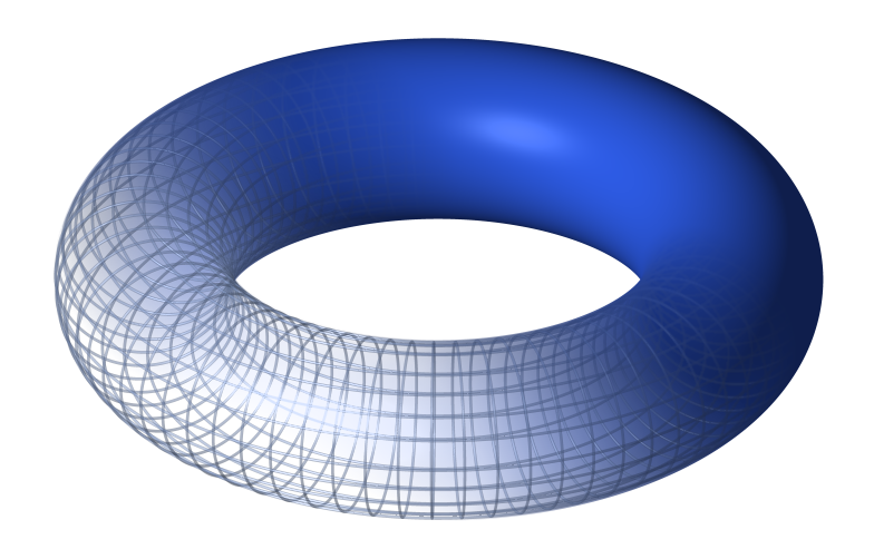
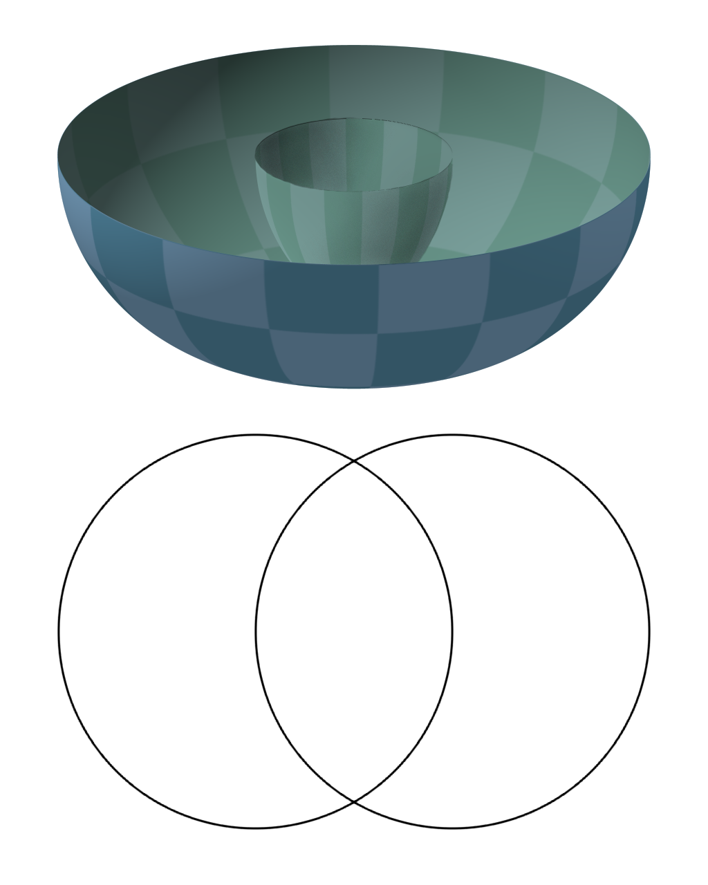
The screen has the shape of a torus, more specifically, a
horned torus. However, we don't use an entire torus but rather the outer mantle only. A torus is an interesting geometrical structure, for example you can divide it into 7 regions that cover the entire torus, each region neighbouring every other. But that's completely irrelevant here. However, here is to illustrate the shape:
 |
| Top: normal torus. bottom: Cross section of the torus we are using. |
The obvious question was: how do I put this shape together. In previous posts I mentioned a skeleton of copper tubes which will be used as a framework, but just as difficult to work as the framework is the actual screen material.
Pufferfish, an Edinburgh based company that does spherical screens, kindly provided me with some of their screen material. Initially my plan was to print a template of each section on paper, transfer it to the screen material and cut the section which are then mounted onto the copper tubes.
As it turns out, the screen material had too many folds (I got it second hand) and didn't allow me to spread it out flat and transfer the pattern. However, I printed the template on canvas paper which appeared to have just the right stiffness for my needs. So I tried.
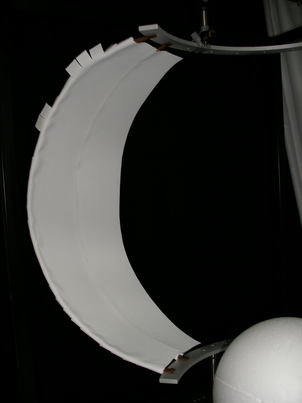
My first attempt of mounting the canvas onto the copper tubes failed as bending the paper around resulted in folds which of course would distort the picture. After trying a few different ways to mount the sections it became obvious that less is definitely more: Mounting the section on 2 points only, the top and the bottom, gives by far the best results. The material is stiff enough to stay in shape by itself when pushed against the copper tubes.
 |
| First failed attempt. Bending the canvas and mounting it all around the tube results in folds. |
 |
| Less is more: mounting the canvas at the top and at the bottom and pushing it against the copper tubes works very well. |
I've used an alternating technique: The first section was mounted to two tubes, one on each side. Then I left a gap and mounted another section. Finally, a slimmer section was mounted between those two, not on the copper tubes however, but on the sections themselves. You can see that in the above picture on the right.
Summary
Screen and mirror put together looks pretty close to what the finaly construction will look like. Here are a few pictures:
 |
| Screen with mirror "hanging" from the ceiling. The mirror is a bit off centre but that will be fixed soon. |
 |
| The back of the screen. It looks less even from the outside that it is from the inside. This is because some of the sections are overlapping. |
Whether everything I've done here will actually work I will find out once the projector is up. Only then I'll know whether my raytracing was correct. Fingers crossed.
One thing you will have noticed in this latest blog entry is that I finally found the "add caption" button for pictures. Yes, that's how computer savvy I am. Now let me get on with programming the virtual reality.
Construction Notes
Mirror
The mirror construction is hanging from the ceiling plate. To achieve that I used a 10mm thick clear acrylic plate and drilled holes at the right places. The mirror is mounted with 4 M6 screws and the entire plate is mounted on 4 M6 threaded rods. I had to cut the rods into the right length, but once that was done it was very easy to mount it using nuts and washers. To attach the flat mirror, 1/2 inch diameter rods and right angle brackets (Thorlabs) where used as shown in the pictures above. The M6 construction cube at the base of the rods has M6 threads on each side which allowed me to mount it to the base plate with M6 screws and then just screw in the rods. The flat mirror itself is mounted on a L-shaped scrap piece of metal I got at the workshop. I drilled a 6.5mm hole into it and mounted it onto an 8-32 to M6 adapter thread with nuts and washers (the standard stud on the end of a 1/2 inch rod is 8-32 but I replaced it by the adapter).
 |
| The clear acrylic base plate. One thing to keep in mind when drilling holes into it: the material heats up quickly, so drill slowly and only drill 1-2 mm at a time then let it cool down briefly. |
 |
| The blackout material. Small holes cut with a knife where the screws will go through. |
 |
| Mirror mounted |
 |
| Mirror and blackout material on the base plate. |
|
|
 |
| The contruction as it is mounted to the ceiling plate. It's very easy to adjust the height like this, just turning the nuts a few times to bring it up or down. |
 |
| The ceiling plate with everything mounted. |
|
| As posted earlier: the final construction. I've got a digital level to bring everyting into the right angle. |
Screen
The screen is a rather tricky construction due to it's uncommon shape. The canvas paper has just enough stiffness to stay in shape without extra support, but any bigger a screen and one probably needs a different approach.
The sections were calculated in Octave (open source equivalent of Mathworks(r) Matlab(r)) and printed on canvas paper. My first Idea was to mount each section to one copper tube and connect it to the next sections with glue or tape. This approach however resulted in ugly folds as described earlier. What worked best for me was mounting one section on two tubes and then connecting those section with slimmer strips. Hope my description isn't too confusing, but if it is feel free to drop me an email. I've mounted the sections to the tubes and to each other using ordinary super glue.
 |
| The leftmost section is mounted on a copper tube on each side. The gap you see in between was covered by a thinner section that was glued to the flaps you see at the top and at the bottom. |
 |
| The section as it was printed on the template. Unless you really like blisters on your hand you should invest in a good pair of scissors. |
 |
| Getting there. |
 |
| Entire screen without the mirror construction. You can see the copper tubes shining through the material, but with any luck that won't be visible once the room is dark and only the projector is shining on it from the inside. |
References:
Chahl, J. S., & Srinivasan, M. V. (1997). Reflective surfaces for panoramic imaging.
Applied Optics,
36(31), 8275-8285. OSA. Retrieved from http://www.ncbi.nlm.nih.gov/pubmed/18264368


No comments:
Post a Comment