
Once again I had a field (half) day at a workshop, this time however it was the physics workshop as opposed to the (very small) neuroscience workshop where I did the black frame. The machinery there instills fear and awe. You wonder what kind of people can tame those machines that appear to be only a step away from growing arms and legs and start crushing everything in their way. There are rumors that on every full moon the technicians sacrifice a virgin's eldest child to appease the machines.
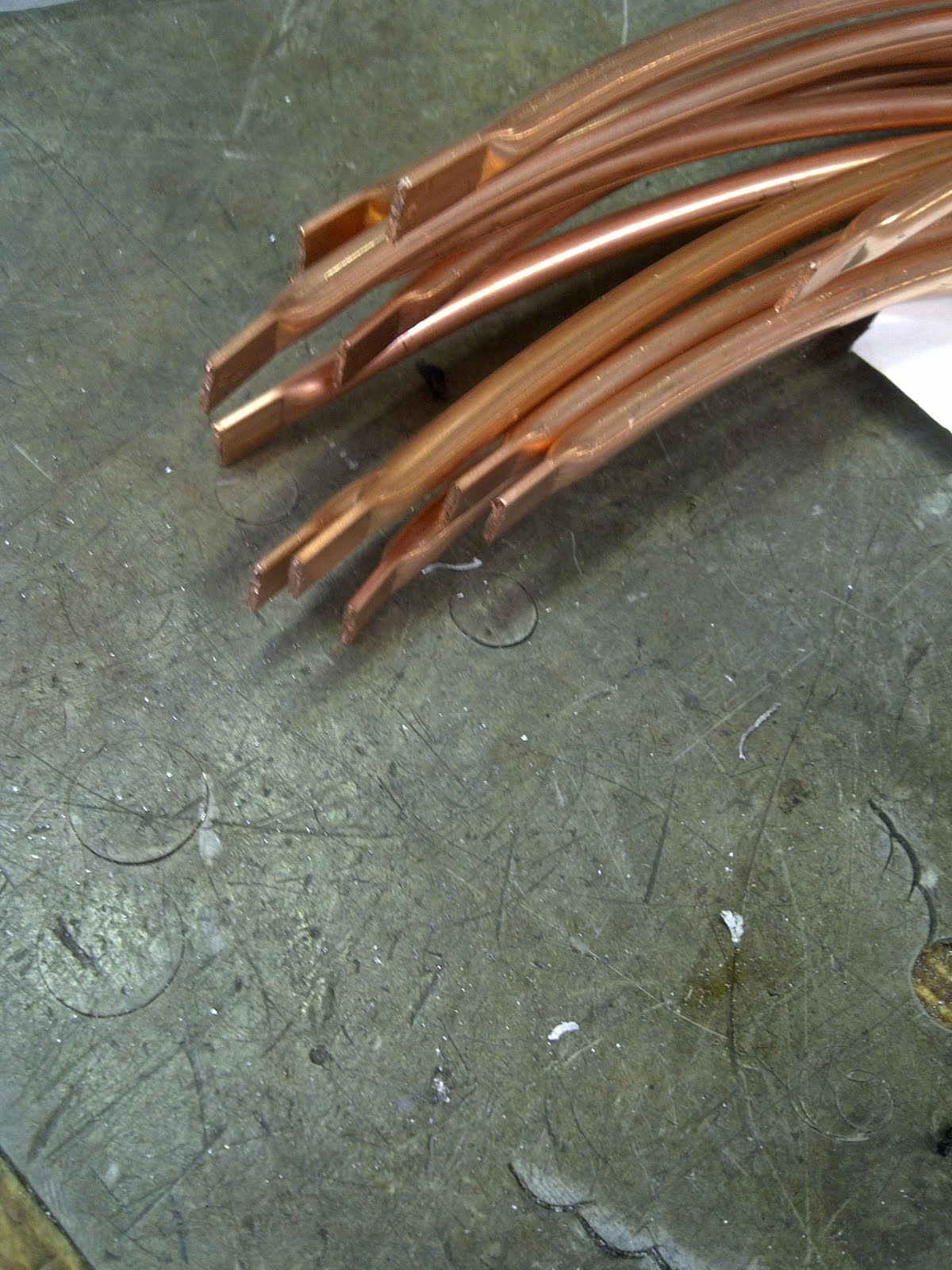
Anyway, after a short chat with the lead engineer we've decided to bend the copper tubes around an appropriate shape. To get that shape we drew a 23cm radius circle on a board and drilled screws halfway in around the perimeter (if you don't know what I mean, look at the pictures below). This allowed me to bend the copper tube around the circle and end up with semi circles of the right size. We placed the screws slightly inside the the 23cm circle because the copper wouldn't stay exactly in the shape I bent it but rather spring back a little bit, so if the circle was exactly 23cm we had ended up with a larger radius.


Above you see the method to bend the tubes around the ring of the screws. Bending full circles allows me to get 2 at a time. My fingertips were hurting after 4 out of 20 semi-circles. The bottom picture shows how I fixed the start of the tube so I don't have to hold it permanently.

21 semi circles. Why 21 when you only need 18? So I have 3 for testing purposes. Why an odd number when you always get 2 at a time? Because I'm a retard and cut one too short.


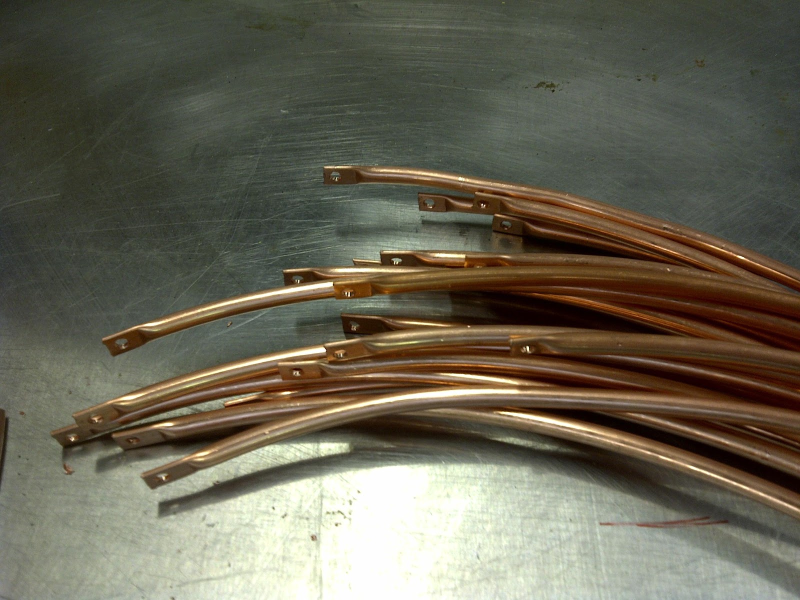
Bottom picture: the result of 5 hours work
Back in the lab I've mounted to top and bottom ring and mounted three tubes to see whether they fit. And they did. Below are a few pictures of the tubes on the rig, for a short while I was tempted to mount all 18 to make it look really nice for the pictures, but putting then first 3 on made me realise that putting all of them on and taking them off again will give me carpal tunnel syndrom.


The tubes fit well and look as I imagined (read: modelled) it.
The next step is to cut the screen sections into shape and mount them on the tubes. In the first instance I will use tape to connect the sections, depending on how visible they are if the projector is on I might have to find a less visible solution. And for those who made it to the very bottom of this post, here is a detailed model of how the mirror will be mounted from the ceiling. It will be hard to oversee the similarity to the Harvey et. al. (2009) setup and I want to give it the according credit at this point. A happy easter everyone!

References:
Harvey, C. D., Collman, F., Dombeck, D. A., & Tank, D. W. (2009). Intracellular dynamics of hippocampal place cells during virtual navigation. Nature, 461(7266), 941-946. Nature Publishing Group. Retrieved from http://www.ncbi.nlm.nih.gov/pubmed/19829374
No comments:
Post a Comment