Tuesday, 21 February 2012

Virtual T-Maze

for a presentation I made a brief video of the virtual reality in action and because I believe in sharing I decided to put it up here as well. What you can see is my hand (cunningly disguised as a mouse) "running" on the treadmill through a T-Maze.

There is still room for improvement for contrast, colour (which mice can't see anyway), etc. but the basics seem to be ok.

Enjoy a fascinating journey through a magical world with stripey and dotted walls. I wonder if mice could learn to play 1st-person Pacman...


Thursday, 26 January 2012

Rig Diagnostics

Every new technique goes through a maturation process in which problems and weaknesses are gradually corrected or accounted for. While I haven't been around personally at the time I can imagine that for example patch clamp recordings have gone through a long process of determining the best material, tip sizes, hardware to minimize mains noise, etc. Virtual reality systems haven't been around for very long and because of their complexity not many groups have acquired one. Hence it is important for me to monitor as many potential sources of problems as possible to avoid wasting time figuring out why something doesn't work.

One thing I've been asked many times was whether the treadmill (and other components) mounted on the airtable cause vibrations in the rest of the system. Knowing that airtables can absorb a fair amount of disturbances my intuitive answer was no. However, vibrations are funny things with hard-to-predict behaviour. Especially if there are frequencies that hit some resonance in the table frame. Further, there will be awake mice running around and nobody (to my knowledge) really knows whether they can cause vibrations in the rig or not. Since I was just playing around with electronics to build my heating mat (it still needs to be boxed up, there will be a post in the near future), I decided to throw together a system to measure vibrations.

The system consists of an accelerometer, an mbed microcontroller, an LCD display from a Nokia 6610 (they come separately, I didn't have to sacrifice an old phone) and a PC. Following is a brief description of the system (with videos!).

All the bits and pieces of the system, explanation below. You can see a second microcontroller in the top left corner, I think I fried that one but I'm not sure yet.


mbed
The central processing unit in this system is an mbed microcontroller. These nifty little things do a lot of stuff but in my case it acts as the middle man between PC and and sensor. It reads information from the sensor on its analog input pins and sends it to the PC via a serial port. There is also a LCD display attached to it which was used for debugging and directly displaying sensor output. To program mbeds you use an online C compiler and simply download the program via a usb connection, its as simple as putting  a file on a USB stick.

mbed on my development board. On the right you see the USB connector which is also used for the serial connection.

Sensor: ADXL 335 Accelerometer
The ADXL 335 including breakout board is a triple-axis accelerometer with a range of +/- 3g. Not a lot but the advantage of this is that it has a higher resolution (300mV/g) as opposed to lower-resolution sensors which cover a wider acceleration-range. The output is fairly straightforward: each pin has an ideal output of 1.5V at 0g (it changes slightly from sensor to sensor but is constant on each individual unit). When acceleration is applied (e.g. move the sensor or just let gravity do its thing) the voltage on the respective pin changes accordingly.

ADXL 335 on a breakout board. I don't want to hear any comments on my soldering job, some of the strands broke and I had to re-solder everything!


Nokia 6610 Colour LCD Display
The display is directly connected to the mbed. There is a library for the mbed which makes it very easy to display stuff on it. It is also used to output some basic data while the mbed is calibrating the sensor so I can see directly whether there is some problem with the sensor. The video shows the display while the sensor is calibrated. Apologies for the blurryness, thats as good as it gets with my phone camera.


PC Software
The software I programmed for the PC has a GUI or Graphical User Interface and was done in Java with RxTx (a MS Windows wrapper for the java.comm API). It reads the information from the mbed via a serial interface and displays a live trace on the screen. The reason for using java and not something less bulky like C is so I can make a nice GUI that gives a good overview over what kind of vibrations there are on the rig. The idea here is to have the program running somewhere on the side during experiments to always have an eye on vibrations. If I'm doing something that's very sensitive to movement (such as recording) and for some reason things go wrong I know whether I can or cannot rule out vibrations. Here is a video showing the z-axis only. I recommend clicking the Youtube button at the bottom right to watch it in a bigger window:


Calibrating the Sensor
The sensitivity of the sensor combined with the fact that nothing is ever 100% still means there are always some changes in sensor output. Also, when the sensor is mounted in a different plane I need to account for the change in direction of gravity. The solution I came up with is that when I hit the calibration button the system takes 100 samples of each axis over a period of 5 seconds and calculates mean and standard deviation. Changes on the pins are then calculated relative to those values (e.g. send an alarm when the change of voltage on a given axis exceeds 3 times standard deviation).
 
Refinements
Two issues have crept up while building this:
  • Sensitivity of the sensor: While it has a good resolution I have yet to test whether it can pick up very small vibrations. With the current system in place however it should be very easy to replace the sensor with a more sensitive unit.
  • Serial connection: The serial stream to the PC is fairly quick, but not quick enough to show high frequency vibrations - I'm getting between 10-15 packages per second. However, the mbed reads the sensor at a much higher frequency, so if I can't figure out a quicker way to transmit the sensor values at a higher frequency I might have analyse the signal on the mbed and send alarms to the PC for high frequency vibrations. A different approach would be to calculate spectrograms on the mbed and only transmit those, thus giving the user a good overview over frequency and power of vibrations instead of a live trace.

Final Words
Whether or not this sensor will provide me with useful information or not has yet to be determined. However, it certainly provides me with a peace of mind knowing that I can monitor movements on my rig.

Sunday, 11 December 2011

Heating Mat DIY (part 1)

Appliances for science are overpriced. Massively. One of those things are heating mats which don't do much other than take the temperature, compare it to the set point and regulate the heat output accordingly. This might sound complicated, but the controller units doing just that have been around for a long time and hence are not very expensive. Certainly not as expensive as companies try to make us believe. Labrigger has a post on DIY heating pads made from industrial parts as made by Taro Ishikawa which I found very interesting and ingenious. And so I embarked on a little adventure and made one for myself.

Things did turn out to be a little tricky at times especially due to my rather rusty knowledge of circuits. Luckily a friend from a collaborating group was happy to explain even the most basic principles of electric circuits with great patience and assisted me as I put everything together. I've bought all my parts from RS Components, in many ways the british equivalent of McCaster-Carr mentioned in the original post.

First off, the idea: What we want is a system that keeps the mouse at a certain temperature, say 38°C. In more technical terms we can say that we have a set point of 38°C and a measured variable (i.e. body temperature) that we can manipulate so it stays at the set point. We manipulate it by changing the temperature of the heating mat. Physiologists will probably think of a simple negative feedback mechansim here, and that's exactly what it is. This could be done manually: just get a thermometer and a heating mat with adjustable heat-output and regulate the heat up or down depending on the body temperature. In fact, many companies sell exactly that kind of system for hundreds of pounds (if not thousands). A better system would be to have a controller that regulates heat-output automatically so we can concentrate on whatever we are doing (surgery for example). The latter is the kind of system I've been working on.

The principal components of the system are:

PID Controller (Control Unit)
In industry, control units that keep a variable at a certain setpoint have been around for a long time, the most abundant of which are PID controllers. I've bought one with a linear DC output (0-10V)  as opposed to most standard models wich come with relays only (RS 701-2788). This would give me the necessary fine-control for a heating mat.

What a beauty. Here you can see it with the mains supply connected.
Heating Mat (actuator)
The heating mat is a rather simple thing, it turns electricity into heat. Wow. 
Also bought from RS (245-528), 50x100mm with a maximum of 5W output at 12V (DC of course). Maximum temperature: 200°C - much more than we need.
  
Thermocouple (sensor)
We use a thermocouple as our temperature indicator. The working principle here is that it will change its voltage depending on the temperature between two conductors. All we need to know is that there are different types and that we need to buy one that our PID controller can read (in our case it can read most types).

In the pictures below you can see a K-type thermocouple, but a T-type probe suitable for mice has been ordered and can easily be replaced.

Non-Inverting Amplifier
The output on our PID controller is 0-10V maximum, but we want 12V. I realise I could probably get away with just using the 0-10V range, but I don't like operating electrical components at their ouput limits. Therefore I put together a simple non-inverting amplifier. The central component is an operational amplifier (RS 652-5678):

The wiring diagram for the opamp.


Building Notes
Here is a quick documentation of the building process:

First, connecting the mains. Care has been taken to
not expose the contacts too much.
It's alive!
The connector on the bottom left is the thermocouple. The two green wires are + and - of the linear output.

In red is the current temperature reading. Below the default set-point of -128.8°C (irrelevant at this stage). Mind you, the reading comes from a work bench heated up by the sun. This is Scotland in December. It's not 23.6°C. Anywhere.


Just to double check, I connected the PID controller to my PC via a NI DAQ and read the linear output. What you see are slow ramps as I increase and decrease the set-point. Clearly, this signal needs some cleaning up, so I put bypass capacitors and a RC low-pass filter between the PID and the opamp. Yes, I took a photo of my screen instead of taking a screenshot. Lazy logic.
Here is a total of the circuit. It's really just a basic non-inverting amplifier with the aforementioned components. The black heatsink in the middle is required to keep the opamp from overheating.
Here you can see the thermocouple taped to the heating mat on the right, and the PID controller on the left.
I also used an oscilloscope (left) to monitor either the output of the PID controller or the amplifier which helped keeping an eye on voltages in the system and finding mistakes.

Next Steps
The current system allows us to keep the heating mat at a certain temperature which is already quite handy. I will go on and tune this system so I can use it in combination with a thermocouple that takes the mouse body temperature directly and regulates the heating mat accordingly. I had no idea how much science has gone into tuning-algorithms for PID controllers (there are actual patents on some), but with a lot of care this should be doable. Bear in mind that we won't use this heating mat around other electrically sensitive equipment, so no precautions to shield mains noise have been taken (yet). Also, I will soldier all this onto a stripboard and box it up so it looks nice and is safe when used with animals, expect an update after christmas. 


Tuesday, 22 November 2011

More Aperture Science

We do what we must because we can. And so I finally constructed the long promised aperture that blocks any unwanted light and shadows from reaching the screen. Up to now I had a brightly lit rectangle with a round shadow on the screen. While it was clear to me that this would be gone in the final version it did confuse many people I presented my work to. Below is a picture of that effect.

Click on the picture to see it full size. To make it clearer I drew a red rectangle around the overshooting light.

 The initial plan was to calculate the exact shape I need to only let light through that will also hit the mirror (see this post for details). However, since the light at the level of the aperture is still unfocused it was difficult to calculate exactly how big the opening had to be to catch all of the overshooting light. Therefore, I decided in favour of a Thorlabs aperture with a maximum opening of 75mm diameter. This way I could close it as far as necessary. It is mounted on the poles that also hold the flat mirror. At this location it is as close to the mirrors/screen as possible (with respect to the path of light), without interfering with the VR projection.


Thorlabs aperture fully opened

The aperture has just the right size. If it had been too small I could have mounted it a bit closer to the projector. This would have meant the picture is even more unfocused which in turn means I would also block more light that is meant for the screen and thus have less contrast/brightness.

The reason why we can't just tape some cardboard on the back of the round mirror to catch excess light is because the light deflected from the convex mirror (better known as Angular Amplification Mirror or AAM, see previous posts for more information) goes right past it. 

Circled in red shows how tightly the light from the AAM shoots past the flat mirror. Adding cardboard here to catch excess light would inevitably block some of the virtual reality as well.
As you can see in the picture of the aperture, the frame of the aperture isn't big enough to block all of the light, so I repurposed an old diary of a colleague (hope she'll never read this) and turned its hardback cover into bits of aperture. In the end it actually looks a lot more professional than it really is.

What a nice day it was indeed.


A masterpiece of handcrafting. My primary school teacher would be proud.
Top bit mounted.
The bottom bit are just two corners of the same material stuck to the aperture with double-sided tape. As you can see in the bottom left corner, to light is overshooting the round mirror now.

With that done the virtual reality looks a lot better and less confusing. The virtual reality is starting to look pretty good now and I keep wondering whether there is a way to upscale this for human use. Not for science, that is.

Wednesday, 19 October 2011

More pictures on Motion Tracking

I didn't show any up close pictures of the new holders in the previous post, here are a few:


 Any questions? Leave a comment or e-mail me.

Monday, 17 October 2011

Apples and Oranges that look like Apples (Motion Tracking 2)

if you haven't done so, read this post first to make more sense the following one.

One of the problems with my initial solution was that the holder for the optical mouse was too big and collided with the treadmill base when I tried to position it. To circumvent this problem I designed a new optical mouse holder that would have a smaller spatial profile. Here is the result:

Computer mouse holder with reduced spatial profile.
When it arrived it fit very well around the optical mouse. Mounting it on my setup worked very well too and it allowed me to mount the mouse where I needed it. In fact it was so nice I wanted to order another one straight away without waiting for the second Dell mouse to arrive. Being overly careful as I am I decided to wait for it, and that was a good decision...

When the new mice arrived I was in for a surprise. I openend it and looked whats inside. The exterior is, for all intents and purposes the same, the inside however isn't. First warning: looking at its USB signature revealed the new mice were made by a different manufacturer. Turning the new mouse on its back showed a slightly different sticker informing you about the technical details nobody really cares about.

Dell mice. The one on the left is the one I gutted first, on the right is a similar looking mouse but with different interior.
The sticker on its belly is the only visible difference from the outside.

The interior is significantly different in shape. The good thing at least was that sensor and lens were the same.
Much worse than the different shapes was the fact that the new mouse would not cooperate with the python code I've developed over about two weeks. If you've tried to read directly from the USB bus before you'll know what a massive pain it is to get the operating system to cooperate with you. More on that in a future post on the software side of the motion tracking. I tried desperately to find the exact same mouse in one of the other offices and exchange it, but, as it turns out, the one I needed was only delivered in a very small time window and is now phased out. Sigh. In any case, this unexpected non-compliance of reality with my expectations caused me to lose about one week to find a new way to read from two mice independently and re-model the mouse holder.

The mouse holder for the new mouse. Small differences, but the re-design nevertheless cost some time.

With all that sorted out I was finally able to mount the second mouse on the setup and test it. Everything worked fine. I have yet to test the spherical treadmill with the virtual reality because I prefer to keep the computer that is running the virtual reality in the office until I finalised development of the virtual reality. Otherwise I'd have to sit in the isolated lab for the rest of the development.

Two mice mounted around the treadmill.
The only thing still missing now is the reward system. I've been waiting for that order for almost two months now and if that company wouldn't be the only one I found that makes those particular valves I would have rejected that order weeks ago. With a bit of luck there will be a post on that soon. Also, I will post information about the software side for the motion tracking system in the not-so-distant future.

Thursday, 15 September 2011

If you don't like what you see, buy a new mirror

Household mirrors are designed to withstand the usual attacks by toddlers/angry teenagers/flying objects and for that end are back-surface coated. This means that you have a sheet of glass on the back of that sheet is the refelctive surface. That way, the reflective coating is protected by the glass which can be conveniently wiped down. This feature however makes it unsuitable to deflect the picture of a projector.

At the point where the projector output hits the mirror it is still unfocused. Before and after the unfocused picture is reflected by the reflective surface it is refracted by the glass. This has the effect of the picture not focussing correctly on the screen anymore, also known as 'ghosting' (see picture below). I didn't do the raytracing of how this happens because I feel exploring that issue in such depth would be a waste of time.

Ghosting effect when using a household mirror. Above and below the actual object are shadows which result from the unfocused picture not being deflected uniformely. Walls and everything else are equally affected, but it's less obvious.

To resolve this issue, we needed a front-surface coated mirror. These are by far more delicate as they can easily scratch. After some research I ordered one from Knightoptical with enhanced aluminium coating (just as a reminder, it's 140mm in diameter). This is, as far as I know, the cheapest coating to reflect the entire spectrum of visible light.


Front surface coated mirror. It even comes with a protective film!
Like the previous mirror, I mounted the mirror on an L-shaped piece of scrap metal. Just make sure to fasten the nut tightly so the mirror doesn't slip.

It is thicker (6mm) than the household mirror I had before, but, to my surprise, wasn't much heavier which I thought could be problem if the right-angle joints I'm using to hold the mirror are not strong enough.


Here is the result: No ghosting anymore. You still see a slight glow or blur around the edges in the picture but that's only the camera struggling with light shining into the lens. You can still see the light overshooting the mirror, but this will be resolved soon too.

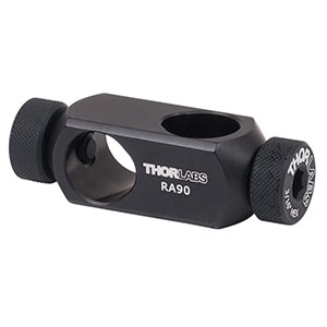
On a sidenote, I've replaced the Thorlabs 90 degree angle joints with Newport joints because you can fasten them much tighter and they easily withstand knocks and vibration. The Thorlabs joints I had to tighten every so often because the screw that presses against the post to hold it comes loose easily. Generally I choose the brand depending on who I feel has the better solution for a given part.


Thorlabs (top) and Newport (bottom) angles. As you can see the Thorlabs joint only has a screw pressing against the post to fasten whereas the Newport joint actually clamps onto the post. Both pictures are property of the respective companies.

Results
With the new mirror installed the ghosting effect is completely gone. Further, because the formerly scattered light is now focused where it should be, contrast and brightness have improved noticeably. However I still think I need to do one or two things to improve picture quality, but this is definitely a step in the right direction.