I didn't show any up close pictures of the new holders in the previous post, here are a few:
Any questions? Leave a comment or e-mail me.
Wednesday, 19 October 2011
Monday, 17 October 2011
Apples and Oranges that look like Apples (Motion Tracking 2)
if you haven't done so, read this post first to make more sense the following one.
One of the problems with my initial solution was that the holder for the optical mouse was too big and collided with the treadmill base when I tried to position it. To circumvent this problem I designed a new optical mouse holder that would have a smaller spatial profile. Here is the result:
![]() |
| Computer mouse holder with reduced spatial profile. |
When it arrived it fit very well around the optical mouse. Mounting it on my setup worked very well too and it allowed me to mount the mouse where I needed it. In fact it was so nice I wanted to order another one straight away without waiting for the second Dell mouse to arrive. Being overly careful as I am I decided to wait for it, and that was a good decision...
When the new mice arrived I was in for a surprise. I openend it and looked whats inside. The exterior is, for all intents and purposes the same, the inside however isn't. First warning: looking at its USB signature revealed the new mice were made by a different manufacturer. Turning the new mouse on its back showed a slightly different sticker informing you about the technical details nobody really cares about.
![]() |
| Dell mice. The one on the left is the one I gutted first, on the right is a similar looking mouse but with different interior. |
![]() |
| The sticker on its belly is the only visible difference from the outside. |
![]() |
| The interior is significantly different in shape. The good thing at least was that sensor and lens were the same. |
Much worse than the different shapes was the fact that the new mouse would not cooperate with the python code I've developed over about two weeks. If you've tried to read directly from the USB bus before you'll know what a massive pain it is to get the operating system to cooperate with you. More on that in a future post on the software side of the motion tracking. I tried desperately to find the exact same mouse in one of the other offices and exchange it, but, as it turns out, the one I needed was only delivered in a very small time window and is now phased out. Sigh. In any case, this unexpected non-compliance of reality with my expectations caused me to lose about one week to find a new way to read from two mice independently and re-model the mouse holder.
![]() |
| The mouse holder for the new mouse. Small differences, but the re-design nevertheless cost some time. |
With all that sorted out I was finally able to mount the second mouse on the setup and test it. Everything worked fine. I have yet to test the spherical treadmill with the virtual reality because I prefer to keep the computer that is running the virtual reality in the office until I finalised development of the virtual reality. Otherwise I'd have to sit in the isolated lab for the rest of the development.
![]() |
| Two mice mounted around the treadmill. |
The only thing still missing now is the reward system. I've been waiting for that order for almost two months now and if that company wouldn't be the only one I found that makes those particular valves I would have rejected that order weeks ago. With a bit of luck there will be a post on that soon. Also, I will post information about the software side for the motion tracking system in the not-so-distant future.
Thursday, 15 September 2011
If you don't like what you see, buy a new mirror
Household mirrors are designed to withstand the usual attacks by toddlers/angry teenagers/flying objects and for that end are back-surface coated. This means that you have a sheet of glass on the back of that sheet is the refelctive surface. That way, the reflective coating is protected by the glass which can be conveniently wiped down. This feature however makes it unsuitable to deflect the picture of a projector.
At the point where the projector output hits the mirror it is still unfocused. Before and after the unfocused picture is reflected by the reflective surface it is refracted by the glass. This has the effect of the picture not focussing correctly on the screen anymore, also known as 'ghosting' (see picture below). I didn't do the raytracing of how this happens because I feel exploring that issue in such depth would be a waste of time.
To resolve this issue, we needed a front-surface coated mirror. These are by far more delicate as they can easily scratch. After some research I ordered one from Knightoptical with enhanced aluminium coating (just as a reminder, it's 140mm in diameter). This is, as far as I know, the cheapest coating to reflect the entire spectrum of visible light.
![]() |
| Front surface coated mirror. It even comes with a protective film! |
![]() |
| Like the previous mirror, I mounted the mirror on an L-shaped piece of scrap metal. Just make sure to fasten the nut tightly so the mirror doesn't slip. |
It is thicker (6mm) than the household mirror I had before, but, to my surprise, wasn't much heavier which I thought could be problem if the right-angle joints I'm using to hold the mirror are not strong enough.
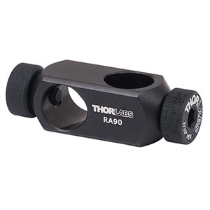
On a sidenote, I've replaced the Thorlabs 90 degree angle joints with Newport joints because you can fasten them much tighter and they easily withstand knocks and vibration. The Thorlabs joints I had to tighten every so often because the screw that presses against the post to hold it comes loose easily. Generally I choose the brand depending on who I feel has the better solution for a given part.
Results
With the new mirror installed the ghosting effect is completely gone. Further, because the formerly scattered light is now focused where it should be, contrast and brightness have improved noticeably. However I still think I need to do one or two things to improve picture quality, but this is definitely a step in the right direction.
Thursday, 1 September 2011
Computer Mouse Surgery (Motion Tracking)
Having a mouse run around the virtual reality requires tracking movement of the mouse (i.e. the treadmill) and updating the location in the virtual reality accordingly. The cheapest system for motion tracking are optical computer mice, placed stationarily at the equator of the spherical treadmill. Apart from being cheap, computer mice are also very easy to interface with the computer. Hölscher et.al. (2005) have succesfully used this system and so have Harvey et.al. (2009), and so will I.
One of the technical difficulties is that the lens has to be very close to the surface of the treadmill, and even small changes in distance can cause problems in tracking motion. Recently, mice with laser instead of normal light are becoming available which are more precise and also seem to tolerate changes of distance between sensor and surface better. After a few tests I decided to use one of the standard issue Dell mice:
![]() |
| The mouse used for motion tracking. Very cost efficient and shows good performance. Dell calls it almost affectionately "Dell Laser Scroll USB (6 buttons scroll) Black Mouse' |
One of the potential downsides of this unit is that it has an inbuilt function to change cursor speed. This might cause problems later on because I need a 1:1 mapping between mouse-movement and input to the computer. I will explain this further in a later post.
First of all I had to remove the housing of the computer mouse and take out the parts that mattered, which is essentially just one PCB board. I would like to show you pictures of the gutting process, but alas I've done that to so many computer mice before this one that I stopped documenting it. My desk is a computer mouse graveyard. Soon enough I will need a second one of these though, at which point I will upload a post with pictures of every step.
After taking out the PCB board I also found out that this mouse has a very handy construction feature: the lens for the laser and camera is directly mounted on the chip (unlike most other mice where it is attached to the housing). So I can just take the PCB out and have a fully functional mouse:
| The underside of the computer mouse PCB. In the centre you can see the lens. |
To allow the mouse to track the motion of the treadmill we need to bring the bottom surface of the lens as close as possible to the surface of the ball without touching it. To do that we need something that holds the PCB board. I guess it's redundant to say that the combination of 3D-modelling software and 3D-printing came in very handy here.
|
|
| The PCB board slots in like this, exposing the lens quite well. I only had to make minor adjustments because apparently my measurements were not 100% correct. |
You can see a small rectangle cut out in the picture above, this is where the connector for the USB cable is located. Simply plug in the cable and then connect it to the computer like you do with a normal mouse (see picture below).
Results
After putting everything together there wasn't much to do other than to mount it on the airtable and see how it works. The mounting angle turned out to be a problem here. The base of the treadmill didn't leave enough space to mount the mouse straight on the equator. This meant I had to angle the computer mouse a bit and mount it further up which in turn required me to mount it vertically rather than horizontally as I had .planned initally. This means I needed more space for the posts, which is suboptimal because there isn't much space left (micromanipulator) and right (head restraint). The next generation of the 3D-model will resolve this problem, at a price of less than £100,- per 3D-print, one or two protoypes are within budget.
A first test showed that movement along the horizontal axis is picked up very well (i.e. running forward and backward), however, movement across is tracked rather poorly. This means I will need a second mouse mounted 90 degrees to the current mouse to pick up sideways movement, as it has been done in the two setups before me (Hölscher et.al. 2005 and Harvey et.al. 2009).
Update
Here is the link to the follow up post: http://mousevr.blogspot.com/2011/10/apples-and-oranges-that-look-like.html
References
1. Harvey CD, Collman F, Dombeck DA, Tank DW. Intracellular dynamics of hippocampal place cells during virtual navigation. Nature. 2009;461(7266):941-6. Available at: http://www.ncbi.nlm.nih.gov/pubmed/19829374 [Accessed September 20, 2010].
2. Hölscher C, Schnee A, Dahmen H, Setia L, Mallot H a. Rats are able to navigate in virtual environments. The Journal of experimental biology. 2005;208(Pt 3):561-9. Available at: http://www.ncbi.nlm.nih.gov/pubmed/15671344 [Accessed June 15, 2011].
Saturday, 6 August 2011
Virtual Reality Virtually Complete
Many hours were spent finding the correct image transformation, but it seems like I've finally made some significant progress. A fair amount of fine tuning is still required, but the transformation and setup seem to be sound.
| Virtual Reality in all its glory. |
To create and and run the virtual reality, Blender 3D (an open source software, free for anyone) is used which further allows me to warp the output. The image transformation function used by us has been contributed to Blender 3D by Dalai Felinto, based on work by Paul Bourke, both of whom can't go unmentioned here. Dalai helped me directly with advice about image transformation and Blender 3D. Further, Hans-Jürgen Dahmen (not mentioned for the first time in this blog), kindly provided me with information on the image transformation used in his setup (Hölscher et. al. 2005).
The Setup
As described previously in this blog, the virtual reality has three components: projector, mirror system and screen. The dimensions and specifications of all of those components are crucial to find the right transformation. But even after all the calculations were done it wasn't easy to arrange all the parts exactly. Mounting the projector in just the right place isn't easy, neither is getting the mirrors at the correct angle and distance relative to each other.
| Projector mount. Quite wobbly, but works if nobody touches it... or exhales too close to it. |
![]() |
| The projector has to be positioned at the point of origin of the ray (top left, where the yellow lines meet) |
| Projector and screen. On the right you can see the pressursied air line taking an adventurous route across the room before it feeds into treadmill and airtable. |
We are using a Vision Techmount ceiling bracket with a 500mm extension pole. It does the job, but a fair amount of play means I will have to go back and stabilise it, otherwise it will be too wobbly. That shouldn't be too difficult though.
Screen and mirror construction are described in detail here.
First tests have shown that the material the screen is made of (canvas paper) doesn't have an ideal surface texture which I think decreases sharpness/contrast. Further, you can see in the picture above that the borders between the paper strips are quite visible which might provide confounding visual stimuli to the mouse. I am looking into ways of mitigating this effect.
The mirrors have been arranged previously to mounting the projector. However, minor adjustments to the flat mirror could be done to correct for slight misalignment of the projector without introducing a noticeable error in the virtual reality.
Image Transformation
This part is what gave me a headache for a while, not because it's so difficult but because I'm very incompetent when it comes to geometry. Paul Bourke's website (link) contains a very comprehensive description of his virtual reality system (which is different to our system but the explanations are nevertheless very helfpul). More than that, the image tranformation functions for his system are available in Blender 3D and can be adapted to work for our system.
The goal is to get a 360° view in a ring-shape. A ring because the centre of the projector output hits the apex of the convex mirror. Concentric rings around the centre translate into horizontal lines on the screen. I hope that makes sense, see pictures below if it doesn't.
To achieve this, the 'spherical panoramic' function of Blender 3D, and the input-output warpmesh are crucial for my application. The spherical panoramic creates a 360° view taken with 6 virtual cameras and stitches them together (similar to a time-lapse panoramic). In a second transformation, an input-output mapping is applied to the picture. In other words, two meshgrids are created: meshgrid A is placed over the spherical panorama and meshgrid B has the shape I need. Each node in grid A has a corresponding node in grid B and the picture is warped into the shape of grid B. I hope this will make more sense after my illustration with many picture below:
![]() |
| This is a total of the maze. The cube is where the observer is positioned, facing the red wall. |
![]() |
| This is the normal perspective view as it appears on the screen initially. Nevermind the monkeyface. |
![]() |
| The ring-shaped mesh. The bottom left node of the square grid corresponds to the bottom node of the inner-most ring of this grid. From there it goes around counter-clockwise. |
![]() |
| And this is the result. The picture is upside down which has got to do with the fact that the projector is mounted upside down. |
The maths behind this is reasonably simple and can be found on Paul Bourke's website (link). First, the square meshgrid is constructed. In our example above it is 12x12, note though that it is actually 12x13, the reason for this is that in the circular meshgrid we have to come full circle, thus the first and the last point on each ring are the same.
For the circular meshgrid one can simply take the square coordinates and calculate sinus and cosinus respectively (more information here):
transmatx(i,j) = y_radmap * cos(theta);
transmaty(i,j) = y_radmap * sin(theta);
(you can find the full listing on the "gridscript listing", found in the blue bar running across the top of the page)
There is more to say about how the transformation is implement in Blender 3D, but I don't feel like writing an essay about this here. If anyone has questions feel free to e-mail me (address is at the top right of this website).
Final Words
Image transformation and virtual reality construction are complete now, what's left to do is a fair amount of fine-tuning. How much fine tuning will depend not only on my subjective sense of what is sufficiently good but will also be based on first tests with animals. After the amount of work and research that has gone into that system I'm happy to see it finall working.
Here are a few impressions of the glowing ball:
References:
Hölscher, C., Schnee, A., Dahmen, H., Setia, L., & Mallot, H. A. (2005). Rats are able to navigate in virtual environments. Journal of Experimental Biology, 208(Pt 3), 561-569. Co Biol. Retrieved from http://www.ncbi.nlm.nih.gov/pubmed/15671344
Thursday, 4 August 2011
A Small Update
This is only a small update, things are going a bit slower right now. I'm working on a few things, the image transformation for the virtual reality, finding the best way to mount the projector, finding a good solution for the reward system and working out the perfect Mojito recipe. And I refined the treadmill a little bit more:
To reduce the noise further I replaced the 1.2mm diameter tubing (20m) by a 1.6mm diameter tube.It is reasonably quiet now (by that I mean a noise level they would experience every day in their cages), but it can be further improved if necessary.
The 1.6mm tube however turns out to be much less flexible than the thinner ones and some measures had to be taken to keep it in place. For that end, Autodesk Inventor was fired up once more to model a bridge that could hold down the tube and can be easily screwed down on the airtable with 25mm M6 hole spacing. I realise, cheaper solutions for this could be found but since I've got a heart for our struggling economy, I contacted the 3D printing company once more. Also, the airtable is getting quite crowded now, so some neatness has its benefits. For £5.- a piece I ordered 5 clamps.
The head fixation system is ready too, unfortunately I can't post details about it as it has been constructed by our local workshop and I'm not holding the copyrights. With a bit of luck however I'll be able to post pictures of the projector and running virtual reality soon.
To reduce the noise further I replaced the 1.2mm diameter tubing (20m) by a 1.6mm diameter tube.It is reasonably quiet now (by that I mean a noise level they would experience every day in their cages), but it can be further improved if necessary.
The 1.6mm tube however turns out to be much less flexible than the thinner ones and some measures had to be taken to keep it in place. For that end, Autodesk Inventor was fired up once more to model a bridge that could hold down the tube and can be easily screwed down on the airtable with 25mm M6 hole spacing. I realise, cheaper solutions for this could be found but since I've got a heart for our struggling economy, I contacted the 3D printing company once more. Also, the airtable is getting quite crowded now, so some neatness has its benefits. For £5.- a piece I ordered 5 clamps.
| Tube clamps. On the right you see a clamp I screwed down too much. |
| An L-joint under the treadmill is absolutely necessary now as the tube is much to rigid to just bend it. Heating up the tube could help to bend it, but for now, this solution works well. |
The head fixation system is ready too, unfortunately I can't post details about it as it has been constructed by our local workshop and I'm not holding the copyrights. With a bit of luck however I'll be able to post pictures of the projector and running virtual reality soon.
Tuesday, 28 June 2011
Trust thy Model (and don't be an idiot).
The 3d model of my setup has been a great help in many ways, one of which is that it is easy to see if parts collide with each other. Great care was taken that there is enough space for all individual parts, with one exception: the projector. The projector has to be mounted from the ceiling as it would induce too much vibration into the setup if we mount it on the frame. Because I have raytracing diagrams I know exactly where the projector has to go and that's where it was placed in the model. It also showed me how it wouldn't fit in where I need the projector. In the picture below you can see the model and how it predicted impending doom. Somehow I was convinced if I just ignore the problem for long enough it will go away. After trying to hold the projector in the right location it became clear that it didn't.
To fix this, the origin of the picture and thus the location of the projector had to be moved. Now there is a spectrum of solutions for this, ranging from clever to... the other extreme. My first attempt was clearly located somewhere close to the opposite end of clever. To re-locate the projector I introduced a second mirror that would deflect the beam away from the black frame, here is the re-calculated diagram:
![]() |
| You can see the mirror + mirror holder at the top. |
This new mirror would do two things: lower the point of origin and change the projector angle, both together mean the projector will not collide with the frame anymore.So I happily modelled the mirror holder, ordered it from a 3D printing company, got the new mirror and put it all together. The new mirror overlapepd the convex mirror at the back, but this wasn't going to be a problem since there is no screen behind the animal.
| The new construction with the new mirror overlapping the convex mirror. This however is irrelevant because that section of the convex mirror is unused. |
In theory this would work, in practice however this new change meant that the projector wouldn't focus on the screen anymore. I haven't investigated exactly why but my suspicion is, because I'm using normal household mirrors which essentially consist of a glass plate and a reflective coating at the back, the light was refracted in a way that made it impossible to focus.
Only then it occured to me that if I just change the angle of the flat mirror underneath the convex mirror by a few degrees I get a much simpler (read: much better) solution that actually works. Arranging the flat mirror in a steeper angle lowers the point of origin and moves it further away from the mirror, if you look at the first figure you can see that this will clear the frame easily. With the palm of my hand across my face I (virtually) tilted the mirror by only 5 degrees and started recalculating the path of light. The result of which you can see here:
![]() |
| The flat mirror was angled by 5 degrees (from 23 to 28 degrees) and lowered by 1.3cm, which moves the point of origin significantly. Right is before, left is after. |
The only downside of this is that the experimenter might need to duck under the projector now while placing animals and exchanging electrodes, but otherwise there are no changes to the setup.
There was one benefit of the mistake I made however, the mirror holder for the second mirror was made on a 3d-printer by an external company. The cost was low (£30) and the quality ok. I wouldn't use it for anything that needs to be precise or clean, but it's ideal if you need something with an odd custom shape. Should I ever have similar requirements I know now where to go.
The next step is to set all of this up in the real world. The difficulty here is arranging all the parts correctly and at the right distances/angles from each other. With all the odd shapes it is difficult to use rulers, tape measures and spirit levels (I've actually got a digital one that gives me a angle readout). Further, getting the projector mount into the right location won't be easy either (how do you mark a point mid-air?). Once all that is done however I'll finally be able to test my virtual reality which I'm programming on the side right now.
Construction Notes
Calculating the requirements for the second mirror wasn't a great effort since the law of reflection is very simple. The centre line (red in the above pictures) was my starting point. I cut it at an arbitrary point somewhere in the top third and dragged the point of origin to a more suitable location. Based on the new angle I calculated the angle of the new mirror and did the raytracing for the entire cone (yellow lines).
The dimensions of the new mirror were calculated by constructing the light cone (see article Aperture Science) and intersecting it at the level of the mirror. This gave me the ellipse that needs to be deflected onto the round mirror underneath the convex mirror. Below you can see that process. What I didn't take into consideration at this point is that the reflective coating of the mirror is at the back, which A) alters the distance from the point of origin and B) refraction of the light changes the angle of the incident ray and therefore also the ray of the reflected ray. All this however was inconsqeuential due to the fact that the projector wouldn't focus on the screen anymore, which I think is too due to effects refraction. I haven't tested that suspicion though as my subsequent solution of changing the angle of the round mirror made the newly introduced mirror redundant.
Modelling the mirror holder was straightforward and it was very easy to order the part from the 3d printing company (3D Creations Lab) since all I had to do was upload the 3D model of the part on their website. The key requirement of the holder is to hold the mirror at the correct angle. The holes at the front are there to reduce the amount of 3D printing material, which lowers the overall cost. I used simple double-sided tape to put the parts together.
| Model and reality. |
Below is another view, holding the camera to the new point of origin. The calculations seem to be correct, from that point of view I can cleary see all of the round mirror, the convex mirror and all of the screen. However, it was difficult to focus the camera.
| Placing the camera at the point of origin showed that the calculations were right, but focussing was difficult. |
After I decided to abandon the new mirror in favour of the simpler solution mentioned earlier, I removed the mirror holder and mirror and everything was back to normal.
Subscribe to:
Posts (Atom)