Thursday, 10 March 2011

Setting up the Treadmill

Knowing that my solution works, it's time to set it up. First of all, a new cup had to be made since the last cup fell victim to my hotwire gun (see last picture of this entry). Why cut in the first place? Space around the treadmill is a very limited luxury so the walls are cut thinner. The hotwire itself was reshaped for more reliability and stability.

For your enjoyment, first off the video of the up and running treadmill. If you click on the youtube logo in the bottom right corner you can watch in in high quality on the youtube website.


The Cup

Here are a few pictures of cutting the walls of the cup:

The soldering gun with the custom-shaped hotwire.

Halfway done.


Going round and round with the hotwire we end up with what you see above.
Again, this looks like poor, amateur work but the mice sure as hell won't care. And neither do I.


The Ball

The polystyrene balls are provided in moulded half-spheres. And for some mysterious reason, the half spheres don't fit together properly. I have spent many a minute wondering why someone designs a mould which probably costs somewhere in the 5-digit range and then makes it so that it doesn't fit. Anyway, out of the box you get this:

A nasty misalignment that might cause the mice to stumble and break their leg. Next stop: prison sentence for animal cruelty. No thanks! Also, the treadmill runs less smooth with this.


To fix this, some fine (p180) sandpaper was used to sand off the excess polystyrene.

And finally some superglue made sure the half spheres won't separate again. Ever.

There is still a small step but with any luck it won't be a problem. If it is, all this will be done again. With more precision and dedication.


The Cup (again)

Now the time has come to make the airsupply a reality. The first prototype had four 6mm tubes and it ran smoothly. The final version has eight 6mm tubes for an even more uniform aircushion. There are many ways to mark 8 holes evenly spaced around the south pole, in our case they are all lying on a ring of about 2cm radius.

A simple wooden screw of appropriate diameter (don't know the exact size, trial and error did the trick) was used to drill the holes. For that end, the screw was turned into the polystyrene a few times and then pulled out without turning. This process was repeated until the wall was penetrated entirely. It's important to not push the screw in as that can result in polystyrene breaking once you get close to the inside of the cup. Once that was done, the tubes can be inserted one by one, see pictures below.

My less than professional way of marking 8 holes: draw a ring, then 2 lines, orthogonal to each other intersection at the centre of the ring and then find the middle between each of the 4 points of the compass (i.e. where the lines intersect the ring). I used a bent wire instead of a pair of compasses.

While drilling the holes the cup was place on a 200mm half sphere to avoid breaking the thin walls


 8 holes drilled with the perfection of a 7-year-old.


Tubing

Now the tubing can be inserted. First, the required length of the tubes was determined, that's pretty straightforward. Inserting the tubes into the cup was a bit trickier, the drilled holes are a very tight fit so that the tubes won't come out easily. Being to rash results in bits breaking of on the inside of the cup. We've pushed the tubes in from the outside to the inside. With hindsight, pushing the tubes in from the inside of the cup to the outside would probably work better.
8 tubes, 6mm diameter.

The inside, it doesn't look perfect, but it works well. This would probably look better if the tubes had been pushed in from the inside to the outside.

Now push the L-joints onto the tubes, all facing into the direction where the airsupply will come from.

On the right is the shut-off valve for the pressurised air coming from the compressor. In two stages this is split into 8 seperate tubes.

Close up of the 1:4 splitter. This picture is only here because I think it looks cool

The final setup, you can see a video of this setup running on The Treadmill page.

With the treadmill up and running an important part of the setup has been completed. Now the only things left to do are the screen, mirrors, virtual reality, programming the virtual reality, designing the headplate and many other things.

Wednesday, 23 February 2011

My Gun is Hot

my soldering gun that is, of course.

To cut the polystyrene-cup into shape, a soldering gun was fitted with a wire of appropriate shape (pictures below). Using a knife might work for the crude shaping, but it doesn't replace hotwire-cutting for more delicate jobs. In my case this was to reduce the thickness of the walls as otherwise there wouldn't be much space left to position the required posts and holders around the treadmill (for head fixation and micromanipulator, see "Mouse Virtual Reality - The Principles").

Using a copper wire wasn't exactly the best choice as copper has very low resistance, but really what we want is the opposite, high resistance means a lot of heat. Also, good conductance means a lot of current is being drawn, so while I was happily cutting away, somewhere in the distance they were probably powering up an additional nuclear reactor to satisfy demand. I'll put this under "lesson learned for the future". Moving on.

As usual, I've documented the process by taking pictures:

 Mains wire with 3 copper strands.

Once you remove the outer insulation, you end up with 3 seperate wires, the one without insulation is the ground, which was subsequently formed into my cutting tool.

This is the soldering gun, with the standard soldering tip removed.
Without much effort you can bend the wire into an appropriate shape and fix it to the tip. Now the hotwire cutter should be ready to go. As became apparent later, my wire was a bit too thin which means it deformed quite easily while cutting and I had to be a lot more careful.

Once the tool is ready we can start with the cutting procedure. The goal is to make a cup like this:

For that end, we take a whole half sphere, and start taking about 2cm off the edge. To guide my cut I cut a small ridge with a knife where my cut should be. I then just followed that ridge with the hot wire:

And got this:

To reduce the spatial profile, some of the wall should be taken off. The shape of the wire can pretty much stay the same for this job. First I've taken out a small portion to place the hot wire properly, and then cut all around the cup in the same fashion I did earlier.


Above is the finished result. It's anything but pretty, it should do the job however. That is, if you don't cut through the wall and have to start all over again

(this is where I cut through the wall).


With this done there is nothing stopping me from putting the cup on my airtable. One of the next posts will contain a decription of the tubing system that will guide pressurised air into the cup.

Wednesday, 16 February 2011

Cheap is good. And works.

After ordering a moulded 200mm sphere and putting it into a cup made out of a 250mm hollow half sphere, it seems  like we've got a working spherical treadmill. Before I post a brief video of the result, some credit must be given out:
 

Patrick Spooner - for lots of useful advice and help
The lady of Graham Sweet Studios - for suggesting that 250mm hollow half spheres might be the right size for the cup


This is the result:


The next few things on my to-do list for the setup are:
- set up the optical mice so that they track the movement of the ball
- set up mirror and screen for the virtual reality
- program the virtual reality environment

Thursday, 10 February 2011

The idea was sound...

The 2nd attempt on a papier mache cup failed (no pictures of yet another failure!). The hotwire-cut polystyrene balls are simply too uneven in shape which caused big cavities between ball and cup.

Luckily, the woman at Graham Sweet Studios (where I purchased the polystyrene balls from) mentioned that the inner diameter of the 250mm hollow-half spheres might just be the right size. So I tried.

I cut about 2cm off the edge of the 250mm half sphere as that should leave enough of the cup for the aircushion to form and at the same time allow more room for uneveness of the ball:


Here is the result:


The result isn't yet convincing, but the key problem here was again the unevenness of the ball rather than the idea. To circumvent this, molded 200mm balls, which come in two hollow halves, have been ordered. With any luck, they will fit nicely.

Friday, 28 January 2011

Number 2 will do (?)

In an attempt to improve my methods another of Andrew's ideas came to mind: expanding foam. Usually you use this to fill gaps in walls. Whatever it touches while it's still wet becomes a sticky mess, but it's great at keeping stuff in shape. So I mixed up some papier mache from the remaining pulp and did this:

Frankly, I had a  hard time not drawing a face on this. The cup is smaller, far from a half-sphere, but should still be suitable to create an aircushion.

After allowing it to dry for about 5 hours (with an electric fan) I topped it off with expanding foam:

Yes, it doesn't look great, but it does the job. I left it overnight to dry and took it off the next day with this result:

It was still wet on the inside, but once it's dry it will get air-inlet holes centered around the south-pole and from hopefully will make the ball hover.

Latex (not the writing software) and how the first attempt failed.

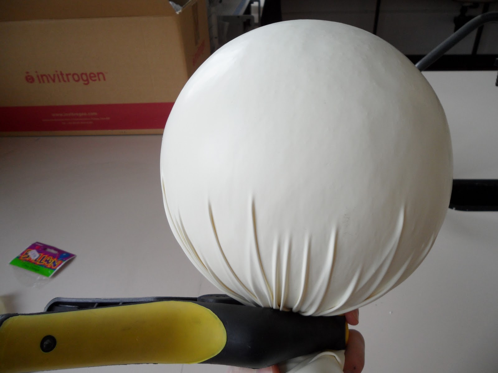
To model the papier mache around the styrofoam ball and yet have some clearance we require something that is very elastic and fits tight. Andrew Downie suggested (industrial) latex, which, as it turns out, was a great idea. It's not easy to fit anything around a sphere without folds, but with enough force, anything is possible:


Put the latex over the ball, grab it at the bottom and twist it until there are no folds anymore. This is easier said that done, but with a bit of trial and error it should be doable. The clamp helped keeping it in position, but you will need patience: it can be VERY frustrating to place the clamp without un-twisting the latex (there is a lot of torque!). Everytime that happens you have to start all  over again.


Take the papier mache and model it around the half-sphere. Easy enough. Or so I thought. To give it even more stability, I gave it some PVA icing, like this:


While the PVA dried, the papier mache underneath didn't, not even a bit despite an electric fan pointing at it for hours. The effect: after two days it was still pretty soft.

To contain the mistake I made, I tried to peel off the layer of PVA:
Which again, wasn't a great idea, the papier mache layer was very thin now and, to my surprise, still wouldn't dry on the inside. When I took it off (take the ball out first, then carefully tear out the latex), it came apart.

That was the sad end of my first attempt.

Papier Mache (how the cool kids do it)

The idea of using papier mache was not mine, Andrew Downie from the Edinburgh University Physics Department raised this idea and he therefore deserves full credit for it.

I followed the recipe I found here. There are some more tips there, so if you want to do it yourself, go look there as well.

Here are a few photos of the papier-mache production process:

Making pulp: anyone who ever managed to cook pasta should have the skills for this step. Tear up newspaper, put it into any kind of pot, pan or beaker and cook it. Whisk it with a standard whisk every 30 minutes to turn the newspaper into mush.


Once it has all come apart, you have to drain the water out of this disgusting soup. A standard kitchen sieve will do, but you will have to use your hands to squeeze the remaining water out of the paper, just dumping it in the sieve won't do by itself.

Once you got most of the water out, you need to scrunch it up (I rolled it between my hands) and dry it. An electric fan can do wonders if you don't have much time.


This stage is rather crucial. Get a cheap blender (I got this one from Argos for £20) and blend the dry newspaper, only small amounts at a time. The difference is huge, you end up with very fluffy and slightly dusty pulp, perfect for papier mache!

Next step: mix it up!

Mixing in the other ingredients is very straightforward, but I made some pictures anyway:
Here is the rest of the party: Sawdust (on the far left, being pushed out of the picture by the pulp), wallpaper paste, boiled linseed oil, PVA, whitening and some water (ignore the huge bottle filled with a dangerous fluid, this is a research facility after all)

essentially what you do is to throw it all together and mix it well. In the original recipe they mix it with a T-shaped mixing bit attached to a drill. If you do that I think you'll end up with a smoother paste.