For your enjoyment, first off the video of the up and running treadmill. If you click on the youtube logo in the bottom right corner you can watch in in high quality on the youtube website.
The Cup
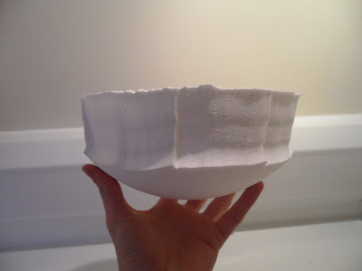
Here are a few pictures of cutting the walls of the cup:
The soldering gun with the custom-shaped hotwire.
Halfway done.
Going round and round with the hotwire we end up with what you see above.
Again, this looks like poor, amateur work but the mice sure as hell won't care. And neither do I.
The Ball
The polystyrene balls are provided in moulded half-spheres. And for some mysterious reason, the half spheres don't fit together properly. I have spent many a minute wondering why someone designs a mould which probably costs somewhere in the 5-digit range and then makes it so that it doesn't fit. Anyway, out of the box you get this:
A nasty misalignment that might cause the mice to stumble and break their leg. Next stop: prison sentence for animal cruelty. No thanks! Also, the treadmill runs less smooth with this.
To fix this, some fine (p180) sandpaper was used to sand off the excess polystyrene.
And finally some superglue made sure the half spheres won't separate again. Ever.
There is still a small step but with any luck it won't be a problem. If it is, all this will be done again. With more precision and dedication.
The Cup (again)
Now the time has come to make the airsupply a reality. The first prototype had four 6mm tubes and it ran smoothly. The final version has eight 6mm tubes for an even more uniform aircushion. There are many ways to mark 8 holes evenly spaced around the south pole, in our case they are all lying on a ring of about 2cm radius.
A simple wooden screw of appropriate diameter (don't know the exact size, trial and error did the trick) was used to drill the holes. For that end, the screw was turned into the polystyrene a few times and then pulled out without turning. This process was repeated until the wall was penetrated entirely. It's important to not push the screw in as that can result in polystyrene breaking once you get close to the inside of the cup. Once that was done, the tubes can be inserted one by one, see pictures below.
My less than professional way of marking 8 holes: draw a ring, then 2 lines, orthogonal to each other intersection at the centre of the ring and then find the middle between each of the 4 points of the compass (i.e. where the lines intersect the ring). I used a bent wire instead of a pair of compasses.
While drilling the holes the cup was place on a 200mm half sphere to avoid breaking the thin walls
8 holes drilled with the perfection of a 7-year-old.
Tubing
Now the tubing can be inserted. First, the required length of the tubes was determined, that's pretty straightforward. Inserting the tubes into the cup was a bit trickier, the drilled holes are a very tight fit so that the tubes won't come out easily. Being to rash results in bits breaking of on the inside of the cup. We've pushed the tubes in from the outside to the inside. With hindsight, pushing the tubes in from the inside of the cup to the outside would probably work better.
8 tubes, 6mm diameter.
The inside, it doesn't look perfect, but it works well. This would probably look better if the tubes had been pushed in from the inside to the outside.
Now push the L-joints onto the tubes, all facing into the direction where the airsupply will come from.
On the right is the shut-off valve for the pressurised air coming from the compressor. In two stages this is split into 8 seperate tubes.
Close up of the 1:4 splitter. This picture is only here because I think it looks cool
The final setup, you can see a video of this setup running on The Treadmill page.
With the treadmill up and running an important part of the setup has been completed. Now the only things left to do are the screen, mirrors, virtual reality, programming the virtual reality, designing the headplate and many other things.


Are your virtual reality environments primarily visual experiences, or do they include additional sensory information such as sound through speakers or headphones?
ReplyDeleteWill you also include tactile information, (aka force feedback)? If you do, what kind of tactile information (electric shock, or vibration from the sphere etc) and will it be a problem with regards to animal rights groups?
Is your virtual reality environment displayed on a computer screen or a special stereoscopic display?
If your experiment was to be done on human beings instead of mice (obviously impossible due to ethical concerns), how would your omnidirectional treadmill design be rectified such as to ensure stability?
I have many more questions, but I will visit another time to ask them.
I hope you will answer my questions.
-Your fellow geek
Dear Melissa,
ReplyDeletethere will be sensory feedback and a reward system, the details of which we haven't decided on yet.
Tactile feedback would be ideal but is also the most difficult the implement given that we can program any kind of virtual reality. In previous studies, airpuffs have been used as mild aversive stimulus, for example when the mouse ran into a wall.
the virtual environment will be displayed on a custom made screen which has a toroidal shape. You can find a bit more information under "Mouse Virtual Reality - The Principles" which you can find in the menu bar under the title.
We haven't considered a human version of this setup yet and I can therefore not answer the question how we would adapt the treadmill for humans.
Feel free to answer any more questions.
-Lukas